
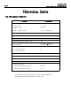
Owner's manual


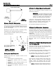


MANUAL RELEASE MECHANISM
Insert the key and turn it counterclockwise one full turn
to disengage the operator’s hydraulic system (see Figure
3). You can now move the gate leaf slowly by hand to
open or close the gate.
Operating the gate leaf by hand is necessary during
installation and is useful during power failures.
You re-engage the hydraulic system by turning the key
clockwise one full turn.
I
NSTALLING THE OPERATOR
Installing the model 402 operator consists of the
following steps:
1. Attaching the rear mounting bracket
2. Attaching the operator to the rear mounting
bracket
3. Attaching the front mounting bracket to the
operator
4. Attaching the operator to the gate leaf
5. Adjusting the hydraulic pressures for the
operator
Page 7
November, 2003
402 Operator And
455 D Control Panel Installation Manual
Turn the key counterclock-
wise 1/2 turn to disengage
the hydraulic drive
Figure 3. The Manual
Release key, bottom view
ATTACH THE REAR MOUNTING BRACKET
Attach the rear mounting bracket according to the
dimensions in Figure 4.
WARNING! You must achieve the A and B
dimensions, dimensions as specified in Figure
4. Modification of the rear bracket may be
necessary to achieve these dimensions (I.e.,
cutting or extending the bracket provided)
If you have a steel gate post, weld the rear bracket
directly to it. If the gate post is made of any other
material, attach the optional mounting plate, with
lag bolts or anchors, and weld the bracket to it.
For an outward swing gate refer to Figure 5.
ATTACH THE MOUNTING HARDWARE
Place the operator so that the red and green pressure
adjusting screws face up. Place the mounting fork (hex
cut up if you have a nylon rear fork) in the operator’s
rear flange, secure with the long brass pin and self-
locking nut.
Attach the fork assembly to the rear mounting bracket
and secure with the short pint, washer, and nut.
Push the front pin through the front mounting bracket
then the piston red to temporarily attach them
together.
ATTACH THE FRONT MOUNTING BRACKET
TO THE OPERATOR
Insert the triangular key over the Manual Release
mechanism on the underside of the operator and
turn the key counterclockwise one turn.
For inward swing, pull the piston completely out and
push it back inward approximately 1/4 “ (6mm).
For outward swing, push the piston in completely
and pull it back out approximately 1/4“ (6mm).
NOTE: Be sure the operator is level and that
the gate is against the closed positive stop.
Hold the front mounting bracket flush against the
gate, mark the location of the front mounting
bracket, remove the operator from the gate.
Remove the front mounting bracket from the piston
rod.
NOTE: Clamping the front mounting bracket at
the marked location before checking the swing,
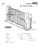
Figure 2.
Positive Stops