per la natura carta riciclata 100% for nature recycled paper 100% pour la nature papier recyclÈ 100% ist umweltfreundlich 100% Altpapier para la naturaleza 100% papel reciclado voor de natuur 100% kringlooppapier 746ER & & 780D 780D 746ER
EC DECLARATION OF CONFORMITY FOR MACHINES (DIRECTIVE 98/37/EC) Manufacturer: FAAC S.p.A. Address: Via Benini, 1 - 40069 Zola Predosa BOLOGNA - ITALY Declares that: Operator mod. 746ER with electronic control unit 780D • is built to be integrated into a machine or to be assembled with other machinery to create a machine under the provisions of Directive 98/37/EC; • conforms to the essential safety requirements of the following EEC directives: 73/23/EEC and subsequent amendment 93/68/EEC.
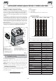
AUTOMATED SYSTEM 746 & ELECTRONIC CONTROL UNIT 780D where: Ta = opening time Tc = closing time Tp = pause time Ti = time of interval between two complete cycles These instructions apply to the following models: 746 ER Z16 - 746 ER Z20 - 746 ER CAT - 746 ER RF The FAAC mod. 746 automated system for sliding gates is an electro-mechanical operator transmitting motion to the sliding leaf via a rack or chain pinion appropriately coupled to the gate.
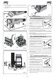
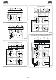
To make the connections efficiently, allow the cables to project by about 40 cm from the hole (Figs.5-6 ref. ) of the foundation plate. 2. DIMENSIONS Fig. 4 Fig. 2 3. ELECTRIC EQUIPMENT (standard system) Fig. 5 Operator 746 with 780D equipment Photocells Key-operated push-button Flashing lamp Radio receiver Fig. 3 4. INSTALLATION OF THE AUTOMATED SYSTEM 4.1. Fig.
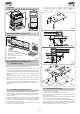
) Secure the gearmotor to the foundation plate, tightening the nuts as in Fig.12. 6) Prepare the operator for manual operating mode as described in chapter 8. Fig. 12 Fig. 8 4.4. INSTALLING THE RACK 4.4.1. Fig. 9 4.4.2. A B STEEL RACK TO WELD (Fig.13) 1) Place the three threaded pawls on the rack element, positioning them at the top of the slot. In this way, the slot play will enable any adjustments to be made. 2) Manually take the leaf into its closing position.
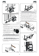
Fig. 19 4.5.2. MOD. 746 ER RF (Figs. 20 - 21) Fig. 15 1) Insert the spring pin on the shaft, using a hammer. 2) Fit the idle transmissions bracket on the gearmotor flange, using the four screws (M5 x 12) and the appropriate washers , in the kit as shown in Fig. 20. 3) Fit the chain pinion on the shaft, making the pinion seats coincide with the spring pin and tighten the screw and the appropriate washers and . 4) Pass the chain as shown in Fig. 21 ref.
5.3. 5. CONTROL BOARD 780D 5.1. DL Led J1 J2 J5 J6 J7 J8 F1 F2 F – + WARNINGS Important: Before attempting any work on the control board (connections, maintenance), always turn off power. - Install, upstream of the system, a differential thermal breaker with adequatetrippingthreshold. - Connect the earth cable to the terminal on J7 connector of the board, and to the bush on the operator (figs. 22 and 40).
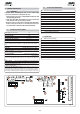
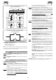
5.4. Opening safety devices: they are tripped when an obstacle is detected only during gate opening movement. They cause immediate closure and resumption of opening motion on release (see programming in par. 5.5.2.) ELECTRIC CONNECTIONS 230Vac 50-60Hz Closing safety devices: they are tripped when an obstacle is detected only during gate closing movement. They cause re-opening, either immediate or on release (see programming in par. 5.5.2.
+ + SAFE CL OP OPEN A + + SAFE CL OP OPEN B OPEN A OPEN B Connection of two pairs of closing photocells and two edge safety devices Connection of a pair of opening photocells Fig. 29 + + SAFE CL OP OPEN B OPEN A Connection of a pair of closing photocells Fig. 32 + + OP CL SAFE Fig.
To install several partial opening pulse generators, connect the N.O. contacts in parallel (fig.35). TX OP/CL FSW OP - Opening safety devices contact (terminal 3): The purpose of the opening safety devices is to protect the leaf movement area during opening. During opening, in the A-AP-S-E-EP logics the safety devices reverse the movement of the gate, or stop and restart the movement when it is released (see advanced programming in Chpt. 5.5.2).
TX -FSW - Negative for power supply to photocell transmitters (terminal 11) If you use this terminal for connecting the negative for supplying power to the photocell transmitters, you may, if necessary, also use the FAIL SAFE function (see advanced programming in Chpt. 5.5.2). If this function is enabled, the equipment checks operation of the photocells before every opening or closing cycle. W.L. - 5.5.
Display Function FORCE: Adjusts Motor thrust. = minimum force = maximum force Default Display If this function is activated, it enables a function test of the photocells before any gate movement. If the test fails (photocells not serviceable signalled by value on the display), the gate does not start moving. OPENING DIRECTION: Indicates the gate opening movement and makes it possible not to change the motor connections on the terminal board.
Display Function Default Display Function OPENING PHOTOCELLS LOGIC: PARTIAL OPENING: Select the tripping mode of the opening photocells. They operate for the opening movement only: they stop the movement and restart it when they are released, or they reverse it immediately. = Reverse immediately to closing = Restart movement on release You can adjust the width of partial leaf opening. Time can be adjusted from to in 1 second steps.
Attention: due to the powerful magnetic fields the supplied magnets produce, the magnets can damage magnetic band components (credit cards, magnetic tapes, floppy disks, etc) and electronic and mechanical equipment (e.g. watches, LCD screens). We advise you not to bring them near to objects that could be damaged if 'immersed' in a magnetic field. 6. START-UP 6.1. ELECTRIC CONNECTIONS Make all electrical connections to the board as in chapter 5, including earthing of the operator (Fig. 40).
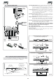
Notes on plate positioning • • • To reduce torque, turn the screw anti-clockwise. Ü The operator is supplied with the clutch set to maximum level. Therefore, you must initially turn the screw anti-clockwise to reach the best setting. To ensure correct operation, allow at least 2 cm from the mechanical stop limit in the gate stop position. Carry out this check after determining the values of the pre- and post-limit switch decelerations (see par. 5.5.2.
Fig. 50 Fig. 47 12.MAINTENANCE Check the operational efficiency of the system at least once every 6 months, especially as regards the efficiency of the safety and release devices (including operator thrust force). 8. MANUAL OPERATION If the gate has to be operated manually due to a power cut or malfunction of the automated system, use the release device as follows: 1) Open the protection door and fit the supplied key in the lock (Fig. 48). 12.1.
33 No effect (1) (3) Closes the leaf (3) OPENING LOCKED Stops operation (3) Closes the leaf (with Closing Safety devices engaged, opens at the 2nd pulse) (3) OPENING LOCKED Closes the leaf (3) LOCKED Re-opens the leaf immediately Stops operation (3) Closes the leaf (with Closing Safety devices engaged, opens at the 2nd pulse) (3) CLOSING OPENING LOCKED Opens leaf for the partial opening time Re-closes the leaf immediately (3) Opens the leaf CLOSED OPEN OPEN-A Logic "E" GATE STATUS O
34 PULSES Stops operation / CLOSING OPENING No effect Reverses to open No effect Opens the leaf OPEN CLOSING OPENING LOCKED Opens the leaf No effect Reverses to open No effect Opens the leaf CLOSED OPEN CLOSING OPENING LOCKED Closes the leaf No effect No effect Closes the leaf No effect OPEN-B (closing) No effect (OPEN A/B disabled) Stops operation No effect (OPEN B disabled) STOP No effect (OPEN A/B disabled) Stops operation No effect (OPEN B disabled) STOP Stops opera
USER’S GUIDE AUTOMATED SYSTEM 746 Read the instructions carefully before using the product and keep them for future consultation. GENERAL SAFETY REGULATIONS If installed and used correctly, the 746 automated system will ensure a high degree of safety. Some simple rules regarding behaviour will avoid any accidental trouble: - Do not stand near the automated system and do not allow children and other people or things to stand there, especially while it is operating.