Owner’s Manual Models 1506 and 1504 Programmable Stand Alone Digital Keypad Entry Devices DoorKing, Inc. 120 Glasgow Avenue Inglewood, California 90301 U.S.A. Phone: 310-645-0023 Fax: 310-641-1586 www.doorking.com P/N 1506-065 REV C, 9/01 Copyright 2001 DoorKing, Inc. All rights reserved.
Page 2
Use this manual with the following models 1506-080, 1506-081, 1506-082, 1506-083, 1506-084, 1506-085, 1506-086, 1506-090, 1506-091, 1506-092, 1506-093, 1506-094, 1506-095, 1506-096, 1504-080, 1504-082, 1504-083, 1504-084, 1504-085 and 1504-086 Digital Keypad Entry Devices with circuit board 1506-010, Rev G and Higher. DoorKing, Inc. reserves the right to make changes in the products described in this manual without notice and without obligation of DoorKing, Inc.
Page 4
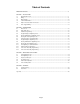
Table of Contents IMPORTANT NOTICES............................................................................................................................................6 SECTION 1 – INSTALLATION 1.1 Mounting Dimensions ...............................................................................................................................7 1.2 Wiring ...............................................................................................................................................
2.15 IMPORTANT NOTICES • Prior to starting the installation, become familiar with the instructions, illustrations and wiring diagrams in this manual. • Never mount this device to a moving gate or gate panel, or next to a gate that causes vibration to the fence, such as a spring-loaded pedestrian gate. Continuous vibration from moving or slamming gates can cause damage to the unit in time.
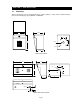
SECTION 1 - INSTALLATION 1.1 Mounting Surface mount units can be mounted directly to a wall or pilaster, or they can be mounted using a gooseneck mounting post (p/n 1200-045 or 1200-046). 5.25 4.375 2.5 3 6 9 # 2.5 2 5 8 0 6.25 1 4 7 * .875 .25 3.375 1506 Surface Mount 10.0 5.25 2.5 4 5 6 7 8 9 * 0 # 2.5 3 3.0 2 6.125 .875 1 5.0 2.875 .875 Dia 1.31 1.
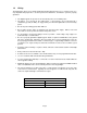
The flush mount keypad consist of two parts, the keypad and the rough-in box. Mount the rough-in box and wiring first, and then install the keypad into the rough-in box. .25 4.375 3 6 9 # 6.625 2 5 8 0 8.375 1 4 7 * .875 4.0 4.25 7.125 .75 FLUSH MOUNT KEYPAD .875 2.56 5.375 4.25 2.0 1.25 1.25 .25 2.25 10-24 STUD 7.0 4.375 2.25 .875 5.625 4.0 ROUGH IN BOX .25 2.125 .75 .875 1.875 2.875 3.
1.2 Wiring The wiring of this device is an extremely important and integral part of the access control system. It is very important that proper wire is used for power and control lines, and that the system is properly grounded. • The digital keypad can operate on 10-16.5 volt AC power, or 12-24 DC power. • The light is set to operate at 16.5 VAC power. If the keypad is to be powered from a solar/battery system (12 VDC), we suggest that you remove the light bulb to conserve battery power.
1.
1.4 Circuit Board Terminal Identification 1. REQUEST TO EXIT – A switch closure to terminal 12 will activate relay 1 for its programmed strike time. DOOR OPEN – A switch closure to terminal 12 will cause the relay that is activated to deactivate 1 second after this input is activated. Can also be used for alarm bypass. TIME ZONE 2 – A switch closure to terminal 11 will lock out all entry codes within the time zone 2 lower and upper boundary.
1.5 Model 1504 Aiphone Intercom Station Connections These wire diagrams are provided for convenience only. For detailed wiring information on Aiphone products, visit their website at www.aiphone.com.
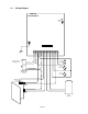
1.6 Slave Keypad Wiring 8-Conductor 22 AWG Shielded Cable 1599-010 Board To Slave Keypad Light To Main Terminals 13 and 14 1506-081 Slave Keypad • Refer to Slave Keypad Instruction Sheet (p/n 1506-066) for instructions on mounting the 1599-010 board onto the 1506-010 circuit board. • Wire terminals 1-8 on the 1599 board to terminals 1-8 on the 1506-081 slave keypad. Pay careful attention to the terminal numbers as they can appear backwards (numbered right to left) when the faceplate is opened.
Page 14
SECTION 2 - PROGRAMMING Keep a record of the programmed codes by completing the tables on pages 24 and 25. 2.1 Master Code The Master Code is a four-digit number that is used to access all programming functions of the digital keypad. The default factory master code is set to 9999. We suggest that you program a new master code once the system is installed. After programming the master code, write it down and keep it in a safe place.
2.4 Programming Four-digit Entry Codes 1. Press *02 and enter the four-digit master code _ _ _ _ (short beep). 2. Enter the four-digit code _ _ _ _ then press * (beep). 3. Repeat step 2 to enter additional entry codes. Note: the number of codes that can be entered is dependant on the memory size ordered. 4. Press 0# together to end the programming step (long beep). 2.5 Erasing Individual Four-digit Entry Codes 1. 2. 3. 4. 2.6 Press *08 and enter the four-digit master code _ _ _ _ (short beep).
2.8 Programming Five-digit Entry Codes 1. Press *09 and enter the four-digit master code _ _ _ _ (short beep). 2. Enter the five-digit code _ _ _ _ _ then press * (beep). 3. Repeat step 2 to enter additional entry codes. Note: a maximum of 6 five-digit entry codes can be programmed. 4. Press 0# together to end the programming step (long beep). 2.9 Erasing Individual Five-digit Entry Codes 1. 2. 3. 4. 2.10 Press *10 and enter the four-digit master code _ _ _ _ (short beep).
2.12 Hold Boundary Programming The entry system hold boundaries establish a set of four-digit entry codes that will latch relay 1 ON, relay 2 ON, or both relay 1 and relay 2 ON (depending on the divide number programmed and the hold boundaries that have been programmed) indefinitely. To un-latch the relay(s), an entry code within the hold boundary is entered on the keypad. NOTE: Hold boundaries can only be established for the four-digit entry codes. Five-digit entry codes have no hold boundaries. 1. 2. 3.
SECTION 3 – OPERATING INSTRUCTIONS 3.1 Four-digit Entry Codes To use a four-digit entry code, the # key must first be pressed then the four-digit code entered on the keypad. Four-digit entry codes can be programmed to operate either relay 1 or relay 2. When a four-digit code is entered on the keypad (preceded by #), the system checks its memory to see if the code is stored. If the four-digit entry code is not stored in the system memory, the relay(s) will not activate.
3.5 Hold Feature Operation The relay hold feature allows a set of four-digit entry codes to latch (or hold) a relay indefinitely. Any four-digit entry code that falls numerically within the hold boundaries will cause relay 1 to activate indefinitely if no four-digit divide number is programmed. If a four-digit divide number is programmed, and the divide number is less than the lower hold boundary, then the four-digit codes within the hold boundary will activate relay 2.
3.6 Time Zone Operation The entry system has two time zone inputs. By using an external timer or switch, access can be denied to a group of four-digit entry codes during desired lockout times. Four-digit entry codes that fall numerically within a time zone boundary will cause a check of the time zone input when the code is entered. If time zone 1 is activated (switch closure across terminals 3 and 11), four-digit entry codes that are within the time zone 1 boundaries will be denied access.
Page 22
SECTION 4 - APPENDIX 4.1 Troubleshooting • Have a good VOM meter to use when checking voltages and continuity. • Check power wiring wire size and distance. distances can cause problems. • Check that the power transformer is rated at 16.5 VAC, 20 VA minimum. SYMPTON Improper wire size and too long wire run POSSIBLE SOLUTION(S) Cannot get into the programming mode. Wrong master code entered. Start over. Waiting too long when entering data. Enter information quickly.
4.2 Data Tables Use the tables below to record data entered into the keypad system.
NAME 4-DIGIT CODE Page 25 NAME 4-DIGIT CODE