Owner’s Manual 1833, 1834, 1835, 1837 PC Programmable Telephone Entry and Access Control Systems DoorKing, Inc. 120 Glasgow Avenue Inglewood, California 90301 U.S.A. Phone: 310-645-0023 Fax: 310-641-1586 www.doorking.com P/N 1835-065 REV R, 10/11 Copyright 2003 DoorKing, Inc. All rights reserved.
Page 2 1835-065-R-10-11
Use this manual with the following models only. 1833, 1834, 1835 and 1837 Telephone Entry Systems, REV C or Higher. DoorKing, Inc. reserves the right to make changes in the products described in this manual without notice and without obligation of DoorKing, Inc. to notify any persons of any such revisions or changes. Additionally, DoorKing, Inc. makes no representations or warranties with respect to this manual. This manual is copyrighted, all rights reserved.
TABLE OF CONTENTS Preface Important Notices......................................................................................................................................................7 General Information ..................................................................................................................................................8 Features ............................................................................................................................................
3.4 3.5 3.6 3.7 3.8 Programming Letters, Numbers and Messages 3.4.1 Programming Letters and Numbers .........................................................................................37 3.4.2 Programming the User Message – 1834, 1835 .......................................................................38 3.4.3 Programming the Instruction Message – 1834, 1835 ..............................................................39 3.4.4 Programming the User Message – 1837 ........................
Section 6 – Maintenance and Trouble Shooting 6.1 Trouble Shooting ......................................................................................................................................61 6.1.1 Page 6 RS-232 Test .............................................................................................................................63 6.1.2 Weigand Test ...........................................................................................................................64 6.1.
IMPORTANT NOTICE FCC - UNITED STATES This equipment has been tested and found to comply with the limits for a class A digital device, pursuant to Part 15 of the FCC Rules and Regulations. These limits are designed to provide reasonable protection against harmful interference when the equipment is operated in a commercial environment.
GENERAL INFORMATION • Prior to beginning the installation of the telephone entry system, we suggest that you become familiar with the instructions, illustrations, and wiring guidelines in this manual. This will help insure that you installation is performed in an efficient and professional manner. • Telcom Access Standards. It is not permissible for customers to use the telcom network lead-in cable to provide the intercom function between the gate and the house.
FEATURES • Can provide service for up to 3000 residents. • Can store up to 8000 card, transmitter or digital PIN codes (not applicable to 1834). • System can be programmed with a PC by modem, RS-232, RS-422 (requires 1508-055 adapters), a LAN connection (requires 1830-175 TCP/IP kit) or via the internet using the Internet Modem Server (use of the IM Server is fee based. Visit http://www.doorking.com/IMServer for more information).
Page 10 1835-065-R-10-11
SECTION 1 - INSTALLATION Order your telephone line at least two weeks prior to the planned installation date. This will assure that a phone line is available when the unit is installed. The telephone company will require the following information from you: Type: Ringer Equivalence: Jack Type: FCC Registration (US): DOC (Canada): Electrical Listing: Touch Tone, Loop Start 0.0 A RJ11C DUF6VT-12874-OT-T 1736 4528 A Complies with U.L.
1.2 Surface Mount Units Surface mount units can be mounted directly to a wall or pilaster, or can be post mounted using a DoorKing Architectural Style mounting post (p/n 1200-037 and 1200-038). Be sure the unit is mounted securely and is not subject to vibration from closing doors or gates. Standard Surface Mount Housing Case and Mounting Hole Dimensions 4.75 10.125 13.0 10.875 .25 DIA 9.0 .875 DIA 1.125 1 .875 2.625 3.25 5.625 11.25 1.625 2.625 .875 DIA DOORKING, INC.
1.3 Surface Mount Units with Recess Box Surface mount units can be semi-flush mounted into a wall or pilaster by using the optional recessmounting box (p/n 1803-150). Be sure the unit is mounted securely and is not subject to vibration from closing doors or gates. Standard Surface Mount Recess Mounting Box 13.375 3.625 1.625 10.125 2.25 3.375 2.187 .437 4.875 10-24 x 1.25 STUD (4 PL) .25 DIA 13.25 8.5 15.25 10.875 11.0 8.375 9.0 9.0 .25 DIA 2.187 1.375 DIA 3.687 1.125 6.0 6.0 3.
1.4 Flush Mount Units Flush mount units are installed into a wall with flush mount kits 1814-165 (stainless) or 1814-166 (gold). Flush mount kits are not included with the entry system. Flush mount units are not designed for direct exposure to the weather. Be sure the unit is mounted securely and is not subject to vibration from closing doors or gates. 1.125 Flush Mount Units 12.0 10.125 1.125 3.0 .875 13.0 13.25 10.875 .25 DIA 2.625 .50 9.0 .875 DIA 2.625 5.625 1.625 11.25 .875 DIA 2.
1.5 Flush Mount Rough-in Box The flush mount installation kit has two parts; the rough-in box and the trim ring. The rough-in box is installed first. Flush Mount Rough-in Box 1.300 (Flush mount rough-in box is included with the 1814-165 and 1814-166 flush mount kits) 3.450 1.914 12.800 3.000 10.120 3.000 3.000 .275 DIA (5 PL) 1.500 1.800 1.125 DIA (3 PL) 3.000 3.000 6.000 .275 DIA (3 PL) 3.400 1.740 3.400 1.800 1.685 14.600 10.886 3.000 10-32 x .75 Stud (4 PL) 1.740 1.
1.6 Flush Mount Trim Ring Flush mount units can be mounted by using the 1814-165 (stainless) or 1814-166 (gold) mounting kit. Flush mounting kits are not included with the unit. Flush mount units are not designed for direct exposure to the weather. Be sure the unit is mounted securely and is not subject to vibration from closing doors or gates. Flush Mount Trim Ring (P/N 1814-165 and 1814-166) 14.700 3.450 10.120 .286 DIA (4 PL) 13.555 16.055 10.886 1.250 1.250 DIA (3 PL) 4.505 3.
1.7 Flush Mount Surface Mounting Kit Flush mount units can be surface mounted by using the optional 1814-152 surface mount trim ring. Flush mount units are not designed for direct exposure to the weather. Be sure that the unit is securely mounted and is not subject to vibration from closing doors or gates. Surface Mount Kit for Flush Style Units 12.0 1.0 2.625 13.5 .375 1.125 DIA Flush Mount Ring 3.0 1.125 SQ Flush Unit 6.0 1.125 .375 7.5 .875 9.0 DOORKING, INC.
1.8 Wall Mount Units Wall mount units are designed to be mounted directly onto a wall without the need of cutting a large hole as is necessary with flush mount units. Be sure the unit is mounted securely and is not subject to vibration from closing doors or gates. Wall Mount Housing Case and Mounting Hole Dimensions 13.25 3.5 10.125 10.875 15.0 .25 DIA 9.0 2.0 .875 DIA 3.625 3.0 3.0 DOORKING, INC.
1.9 Memory Chip Installation The telephone entry system is shipped with the memory chips already installed in the unit. However, if you need to change the memory chips (to match an older unit, for example), follow the instructions below. CAUTION!! Do not install the memory chips with power to the telephone entry system turned on. Attempting to install the memory chips with power on will irrevocably damage the chips. Memory chips are a static sensitive component.
1.10 Postal Lock Installation At some locations, such as gated communities, it will be necessary to provide access to the mail carrier so that they can deliver the mail. Mail carrier access will be provided by the installation of an Arrow Postal Lock. This is the same lock that the Post Office uses for gang mailboxes. These locks are not available to the public.
SECTION 2 – WIRING Prior to installing wiring to the telephone entry system, we suggest that you become familiar with the instructions, illustrations, and wiring guidelines in this manual. This will help insure that you installation is performed in an efficient and professional manner. The wiring of the telephone entry panel is an extremely important and integral part of the overall access control system.
2.1 Wiring Guidelines Do not run high voltage (115 V) power lines and communication lines in the same conduit. These should be in separate conduits at least six (6) inches apart. Be sure that all phone line wiring is twisted and completely isolated from ground. Use only the supplied 16.5 VAC (or U.L. listed equivalent) to power the entry system. An Inherently Protected Transformer must be used to power this device. If a substitute transformer is used, it must be listed by a recognized testing laboratory.
2.2 Terminal Descriptions MAIN 1 DESCRIPTION Phone Line Connection – 800 ft. maximum with 24 AWG wire; 1600 ft. maximum with 22 AWG wire. 2 Phone Line Connection – 800 ft. maximum with 24 AWG wire; 1600 ft. maximum with 22 AWG wire. 3 Earth Ground Only. 4 Switch Input. A closure between terminals 4 and 6 will cause the designated relay(s) to activate for the programmed strike time or dial a phone number – see 3.2.6. The Postal Switch is connected here. 5 Microphone Input.
2.3 Wiring Detail 2.3.1 Controller Only 30 Series Controller Detail Wiring 6 1 2 3 4 5 6 RS 232 Connection Elevator Control 7 1 2 3 DATA 1 DATA 0 COMMON WHT GRN BLK 20 21 22 ELEVATOR CONTROL 2348-010 16 Central Office phone line - touch tone, loop start. 2 A switch closure across terminals 4 & 6 will activate relay 1 for its programmed strike time. 3 Battery Backup - separate batteries required for phone system and weigand terminals. 4 16 Volt, 20 VA UL Listed Transformer.
2.3.2 Controller & Expansion Boards 1-8 30 Series Controller to 2351-010 Expansion Boards 1-8 Detail Wiring RS 232 Connection Elevator Control 1 2 3 12 14 13 12 11 Auxiliary Terminals NOTES: Controller main terminals 15-16-17 = SYSTEM RELAY 1. Controller main terminals 13-14 = SYSTEM RELAY 2.
2.3.
2.4 RS-232 Cable Connection RED BLACK WHITE BROWN GREEN SHIELD P/N 1818-040 5 9 1 Female End 6 1 2 3 4 5 6 Connector on 30 Series Circuit Boards BOARD TERMINALS DB - 9 PINS DB - 25 PINS 1 3 2 Transmit Data 2 2 3 Receive Data 3 7 4 Request to Send 4 8 5 Clear to Send 5 5 7 Signal Ground - Shell 6 FUNCTION Not Used DOORKING, INC., INGLEWOOD, CA 90301 Title: Date: 1835-065-R-10-11 Detail Wiring - 30 Series RS-232 Connector 6/11 Dwg. No. M1835-065-5 Rev.
Page 28 1835-065-R-10-11
SECTION 3 – PROGRAMMING IMPORTANT! Many of the advanced features available with this telephone entry system cannot be programmed from the system keypad. These features include relay hold open time zones, security levels, elevator control options and programming via the internet using DKS servers. If any of these features are used, the system must be programmed with the DoorKing Remote Account Manager for Windows software, VERSION 6.3.b or higher.
3.1.2 Programming from the Keypad Follow the programming instructions as described in each section of this manual. The system will prompt you with short tones (beep) when programming steps have been followed correctly, and with a long tone (beeeeeep) when the programming step is ended. The display will also assist you in viewing the information that you are programming. It is highly recommended that you complete the resident listing in the appendix prior to starting any programming from the keypad.
3.2 Programming with a PC Prior to programming the PC Programmable Telephone Entry System with the DoorKing Remote Account Manager for Windows software and the user supplied PC, the system must have the MASTER CODE programmed into it. Also, the factory default for the number of area codes is 10. If more than 10 area codes are required, this must be programmed at the unit (see 3.2.2). The master code and number of area codes cannot be set with the PC and must be programmed from the system keypad.
3.2.3 Programming for Call-up Operation This feature is only used when the telephone entry system is interfaced with a DoorKing 1816 or 1820 Telephone Intercom system under certain special applications. The factory setting for this feature is OFF. Do not change this feature to ON. Refer to the 1816 / 1820 Installation Manual, and check with your DoorKing representative on the special applications that this feature is used for. Factory Setting = OFF 1. 2. 3. 3.2.
3.2.7 Switch Input Function The following programming sequence sets the switch input (terminals 4 and 6) to either activate a relay(s) or call the phone number programmed in directory code 0, 00, 000 or 0000. Refer to section 3.3.4 to determine which relay(s) will activate when the switch input is activated. This feature is available on Rev K boards or higher. Factory setting = 0 (switch input activates relay) 1. Press * 1 8 and then enter the four digit master code _ _ _ _ (beep).
3.3 General Programming Proceed with the programming steps on the following pages only if PC programming will not be used. 3.3.1 Relay Strike Time These steps will program Relay 0 (not applicable to the 1834), Relay 1 and Relay 2 strike times. Strike times can be programmed from 1/4 second (enter 00 in step 4) up to 99 seconds by entering the desired time in seconds. If Tracker expansion boards are going to be used with this system, set Relay 2 strike time to 00 for Tracker boards 1-8.
3.3.3 Tone Open Numbers These steps will program the tone open numbers for relays 0, 1 and 2. You will need to enter a fourdigit number (see chart below) to set the relay functions. If a function is not desired, enter # in place of a number. For example, if you want the relay to have a momentary activation function only, and you want the relay to activate when the number 9 is pressed, enter 9 # # # in step 4. Do not duplicate tone open numbers, i.e., don’t set relay 0, 1, and 2 tone-open numbers all to 9.
3.3.5 Touch-tone / Rotary-dial This programming sequence will set the telephone entry system to dial out in either a touch-tone or rotary format. Generally, this will be set for touch-tone. Factory setting = touch-tone. 1. 2. 3. 3.3.6 Press *07 and enter the four digit MASTER CODE _ _ _ _ (beep). Enter 0* (beep) for touch-tone or enter 1* (beep) for rotary. Press 0# TOGETHER to end this programming step (beeeeeep).
3.4 Programming Letters, Numbers and Messages These programming steps apply only to the 1834, 1835 and 1837 systems. The keypad on these systems have all the letters of the alphabet, the numbers 0 through 9, and a space key printed on it. This allows the keypad to be used to program all names and numbers into the systems electronic directory. NOTE: Names should not be programmed from a remote location using a touch-tone telephone. 3.4.
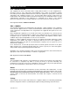
3.4.2 Programming the User Message – 1834, 1835 Systems The user message, followed by the instruction message, scrolls across the screen from right to left when the system is not in use. Both the user and instruction message can be programmed to display your own message. The user message can be a maximum of 48 characters (spaces count as a character) and is entered into the system memory in three blocks. The first two blocks contain 20 characters while the third block contains 8 characters.
3.4.3 Programming the Instruction Message – 1834, 1835 Systems The instruction message scrolls across the screen from right to left when the system is not in use and follows the user message programmed in 3.4.2. The instruction message can be a maximum of 52 characters (spaces count as a character) and is entered into the system memory in three blocks. The first two blocks contain 20 characters while the third block contains 12 characters.
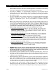
3.4.4 Programming the User Message – 1837 Systems The user message is displayed on the top four lines of the 1837 display. This message can be a maximum of 80 characters (spaces count as a character) and is entered into the system memory in four blocks. The example below shows how the sample message was divided into four blocks and centered on the screen. Use the blank matrix to organize your own message. Only upper case letters, numbers and spaces can be programmed from the system keypad.
3.4.5 Programming the Instruction Message – 1837 Systems The instruction message is displayed on the bottom four lines of the 1837 display. This message can be a maximum of 80 characters (spaces count as a character) and is entered into the system memory in four blocks. The example below shows how the sample instruction message was divided into four blocks and centered on the screen. Use the blank matrix to organize your own message.
3.5 Programming Phone Numbers and Names Before beginning manual programming of this telephone entry system from the keypad, it is strongly recommended that the resident log sheets in the back of this manual be competed in their entirety. This will make programming easier and can be used as a reference when entering phone numbers, names, entry codes and device numbers.
3.5.1 Programming the Directory Code Length This programming sequence sets the directory code length to 1 - 2 - 3 or 4 digits. If 11 or more resident names or telephone numbers are going to be programmed into the system, the directory code must be at least two-digits. If 101 or more resident names or telephone numbers are going to be programmed, the directory code must be at least three-digits.
3.5.3 Programming Area Codes Up to 10 (REV D and lower boards) or 255 (REV E and higher boards) different area codes can be programmed depending on how the system was setup in programming instruction 3.2.2. Program area codes when 10-digit or long distance calling is required. Area code pointers are referenced 0 – 9 in step 2 (for a total of 10) when the system is set for 10 area codes, or they are referenced 000 – 254 in step 2A (for a total of 255) when the system is set for 255 area codes.
3.5.5 Programming Names (1834, 1835, 1837 Systems Only) In this section, names will be programmed into the system. Names are referenced to a phone number by entering the directory code that the person’s phone number has been programmed to. 1. 2. 3. 4. 5. 6. 7. 3.5.6 Press *66 and enter the four-digit MASTER CODE _ _ _ _ (beep). Enter the directory code (1, 2, 3 or 4 digits depending on what was programmed in 3.5.1) then press * (beep).
3.5.8 Delete Area Codes This program sequence deletes area code numbers that have been programmed into the system. 1. 2. 2A. 3. 4. 5. 3.5.9 Press *24 and enter the four-digit MASTER CODE _ _ _ _ (beep). When the system is set for 10 area codes, the display will show 0 – 9 AAC POINTER. When the system is set for 255 area codes, the display will show 000 – 254 AAC POINTER. Enter the area code pointer (0 – 9 when set for 10 area codes) _ then press * (beep). The display will show 4 DIGIT AREA CODE.
3.5.11 Touch Tone Dialing Pause During touch-tone dialing, the system (by default) places a 2 second pause after dialing a line access code (9 in a PBX system for example) and after the area code. For example: 9 (2 second pause) 1310 (2 second pause) 6450023 The 2 second pause can be removed by programming 0 into the steps below. In this example, the system would simply dial out the line access code (9), area code (1310) and phone number (6450023) without any pauses.
3.6 Programming Device Codes (1833, 1835, 1837 Only) Device codes must be five (5) digits in length and are typically card and transmitter codes. Each device code that you enter is assigned to the directory code that you select. Up to 25 device numbers can be entered under a single directory code, up to a maximum of 8,000 for the system. You cannot duplicate device codes. 3.6.1 Programming Device Codes This program sequence enters device (card, transmitter, digital) codes into the system memory. 1. 2.
3.7 Programming Four Digit Entry Codes Four digit entry codes are entered on the system keypad preceded by # to allow the resident access. Do not confuse four-digit entry codes with a five-digit device code entered from a weigand keypad. 3.7.1 1. 2. 3. 4. 5. 3.7.2 1. 2. 3. 4. 5. 3.7.3 Programming Four Digit Entry Codes Press *02 and enter the four-digit MASTER CODE _ _ _ _ (beep). Enter the directory code (1, 2, 3 or 4 digits depending on what was programmed in 3.5.1) then press * (beep).
3.8 Anti-pass Back (1833, 1835, 1837 with APB Chip Set Only) The programming steps below will allow you to set up and program some basic functions for the antipass back feature. However, you must set up the IN and OUT relay programming table in the Remote Account Manager software. Anti-Pass Back tables cannot be set from the keypad. Refer to manual 1835-066. 3.8.1 Programming the Anti-Pass Back Mode Anti-Pass Back (APB) can be set to operate in one of three different modes.
SECTION 4 – ADJUSTMENTS 30 Series Control Board Adjustments 1 2 3 4 5 6 13 1 2 3 2 3 7 1 11 6 12 14 13 12 11 10 9 8 7 6 5 4 3 2 1 NO NC COM 4 8 5 14 9 15 1 2 3 4 5 6 7 8 9 10 11 12 13 14 15 16 17 18 19 20 10 1 Feedback 10 Main Terminal Strip 2 Speaker Volume 11 Auxiliary Terminal Strip 3 Microphone Volume 12 Elevator Control Terminal Strip 4 Click Sensitivity 13 RS 232 Terminal Strip 5 Master Code Toggle Switch 14 Relay 0 Terminals 6 Hands Free (HF) /
4.1 Speaker Volume, Microphone and Feedback Speaker volume, microphone volume and feedback all interact with each other to affect the audio performance of the system. Use the following steps to set these adjustments. 1. Open the front of the telephone entry system and locate the speaker volume, microphone volume and feedback adjustments (see page 47). 2. Set the speaker volume about 1/3 from full counter-clockwise. 3. Set the microphone volume to 1/2. 4.
4.4 Back-light Cutoff 1. This is a factory set adjustment and should not be adjusted in the field. 4.5 Master Code Switch 1. The master code switch is left in the off position for normal operation. Turn the master code switch on when setting the system master code. See programming instructions to set the system master code. If the master code switch is turned on and a new master code is not entered, the system will sound a long tone after approximately 30 seconds.
Page 54 1835-065-R-10-11
SECTION 5 – OPERATING INSTRUCTIONS 5.1 Guest Instructions Instructions on the telephone entry systems guide guest on the usage of the system and how to locate and call the resident that they wish to visit. The 1834, 1835 and 1837 systems utilize A and Z scroll buttons that a guest will use to locate the resident that they are wishing to visit. Pushing the A button will cause the resident directory to scroll up while pushing the Z button causes the resident directory to scroll down.
5.2 Resident Instructions Resident control of the door or gate that the telephone entry system controls is limited to opening the door or gate in response to a call from a guest, or they may open the door or gate by using their assigned four-digit entry code. A resident instruction sheet is included in the back of this manual and may be copied and passed out to your residents. 5.2.
5.3 System Administrator The administrator can perform the following operations from a remote location using a touch tone telephone. You must know the phone number of the system and the system master code. 5.3.1 Opening from a Remote Location 1. Call the telephone number that the entry system is installed on. The system will answer with a short tone (beep). 2. Press *16 and enter the four-digit MASTER CODE _ _ _ _ (beep). 3. Press the desired tone open number _ (beep). NOTE: Refer to 3.3.
5.3.3 Relay Check The telephone entry system can be called and a check can be made to determine if any of the relays in the system are in a "hold open" mode. This check can be useful if yourr gate (or door) is held open and you suspect that the telephone entry system relay may be the cause. 1. Call the telephone number that the entry system is installed on. The system will answer with a short tone (beep). 2. Press *16 and enter the four-digit MASTER CODE _ _ _ _ (beep). 3.
5.4 Miscellaneous Operating Instructions 5.4.1 Talk Time The talk time for directory codes 0, 00, 000, 0000 and 1, 01, 001, 0001 is factory set to 4 minutes 15 seconds and cannot be changed. These directory codes should be reserved for use with management or emergency phone numbers that typically require longer talk times.
Page 60 1835-065-R-10-11
SECTION 6 – MAINTENANCE The DoorKing telephone entry system is essentially a maintenance free device. When the unit is properly installed, it should provide years of trouble free service. Maintenance is limited to updating the directory and phone number and/or entry codes when residents move in or out. The faceplate of the unit should be cleaned on a regular basis to keep contaminants in the air from sticking to the surface and possibly causing pitting.
SYMPTON Cannot get into programming mode. POSSIBLE SOLUTION(S) • Wrong master code entered. Start over. • Waiting too long between pushing buttons. Enter information quicker. • Keypad is not plugged into board correctly. Cable points down. • Memory chips are installed upside down. System emits a long tone and cancels programming. • Waiting too long between pushing buttons. • Forgetting to press # first when programming. Keypad is dead. • No power. Check for 16 VAC input power.
SYMPTON POSSIBLE SOLUTION(S) Four-digit entry codes will not work. • Forgetting to press # first. • Re-program the entry code ranges (3.7.3). Entry codes will not activate relay 0. • Re-program relay 0 low and high ranges (3.7.3). Entry codes will not activate relay 1. • Re-program relay 1 low and high ranges (3.7.3). Entry codes will not activate relay 2. • Re-program relay 2 low and high ranges (3.7.3). System emits a beep every 30 seconds. • Master code switch is in the ON position (4.
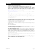
6.1.2 Weigand Test (1835, 1837 Systems Only) This programming sequence will allow you to view the weigand data on the display as it is received by the control board. This will allow you to verify that the weigand device is functioning properly. 1. 2. 3. 4. 5. 6.1.3 Press *82 and enter the four-digit master code _ _ _ _ (beep). Enter 9 9 9 9 * (beep).
6.1.4 Elevator Board / Floor Hardware Test This testing sequence will allow you to check activation of individual relays on the elevator control board(s) and will confirm communication between the telephone entry system circuit board and the elevator control board(s). 1. Press *77 and enter the four-digit master code _ _ _ _ (beep). The display will show: WHICH ELEVATOR? (1835 - 1837 systems only). 2. Enter the elevator shaft number (1, 2, 3 or 4) _ , then press * (beep).
6.2 Accessories Surface Trim Ring Flush Kit Flush Ring Stainless Steel Case Surge Suppressers Mounting Post Telephone Test Set Battery Tracker Boards RS-232 Cable Elevator Board TCP/IP Kit Page 66 Use to recess a surface mount unit into a wall or column. P/N 1803-150. Use to install flush style units into a wall or column. Kit includes rough in back box and trim ring. P/N 1814-165 comes with stainless steel trim ring. P/N 1814-166 comes with gold plated trim ring.
6.3 Log Tables Complete the information in the tables on the following pages to maintain a record of the information that has been programmed into the telephone entry system if the system IS NOT being programmed from a PC. If PC programming is being utilized, there is no reason to maintain these log sheets since the PC will maintain a complete record of the information that has been programmed. Make copies of the resident log sheet so that you have enough to complete a listing of all residents and data.
AREA CODE POINTERS PAGE 1 (System set to 255 area codes) Pointer Area Code Pointer Area Code Pointer Area Code Pointer Area Code Pointer 001 027 053 079 105 002 028 054 080 106 003 029 055 081 107 004 030 056 082 108 005 031 057 083 109 006 032 058 084 110 007 033 059 085 111 008 034 060 086 112 009 035 061 087 113 010 036 062 088 114 011 037 063 089 115 012 038 064 090 116 013 039 065 091 117 014 040 066 092 118 015 041 067 0
AREA CODE POINTERS PAGE 2 (System set to 255 area codes) Pointer Area Code Pointer Area Code Pointer Area Code Pointer Area Code Pointer 131 157 183 209 235 132 158 184 210 236 133 159 185 211 237 134 160 186 212 238 135 161 187 213 239 136 162 188 214 240 137 163 189 215 241 138 164 190 216 242 139 165 191 217 243 140 166 192 218 244 141 167 193 219 245 142 168 194 220 246 143 169 195 221 247 144 170 196 222 248 145 171 197 2
NAME AAC PHONE NUMBER DIR CODE ENT CODE DEVICE CODE SEC LEVEL FL ER Make additional copies of this table as needed.
Resident Instruction Sheet Your building / community has been equipped with a DoorKing Telephone Entry System that will provide communication for your guest from the lobby door / gated entrance to your home by use of the local telephone network.