International Electronics, Inc.
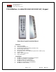
q Section 1: Unpacking and checking the packing list Open the box, and inside you will find: Keypad: Harnesses: Wrenches: Hardware: (1) 212iLM Mullion keypad (1) 8 Conductor wire harness (1) Standard 5/64 allen wrench (1) Hardware Pack containing: (2) 8 x1¼” Panhead Slotted Machine Screw; (2) 8 x 1¼” Round Head Wood Screw; (2) 6-8 x ¾” Plastic Anchor, (1) 212iLM mounting template.
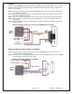
1. Attach the 8-conductor wire harness to the plug in connector on the back of the 212iLM Mullion. 2. Next you will need to attach the relay wires (white/yellow, blue, and brown) to the wire run that is connected to the locking device. 3. The Red and Black wires are connected to the power supply last, BEFORE the power is turned on. Connect positive of the supply to the Red wire and negative to the Black wire.
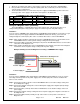
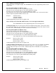
Example of Wiring to a Electro-Magnetic Lock Using a SEPARATE Power Supply: Blue =Common 212iLM Wire Harness White/Yellow = Normally Closed _ To 212iLM Power Supply V+ V- + Red Black To Lock V+ Power Supply V- Wiring to an Electric Strike: (see below) The 212iLM Mullion is equipped with a Form C, Dry contact relay on board. This means that there is no voltage running through the relay (until you supply the common leg of the relay with voltage).
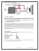
Situation 2: If you are using a separate power supply with the 212iLM Mullion and the Electric Strike, you need to run voltage from the positive of the power supply to the Brown (normally open) wire on the 8 conductor wire harness of the 212iLM. Step 1: Connect the Positive (red) wire on the 212iLM Mullion harness to Positive voltage coming from the 212iLM power supply. Step 2: Connect the Negative voltage wire on the 212iLM power supply to the Negative (black) voltage wire on the 212iLM power supply.
Wiring to a Request to Exit (Push to release): The 212iLM Mullion keypad may be wired to accept an input from a remote-switching device. This is a momentary input that will engage the main relay for the same amount of time that the master code is programmed with. This input requires a normally open, momentary closure between the White with a Black trace wire and the Black wire. The only time the REX won't follow the main relay time is if the Master code has been programmed to latch the main relay.
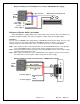
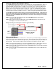
Example of wiring to a Bell or Speaker: To Power Supply V+ Red To Power Supply VBlack _ + 212iLM Wire Harness White (B) Normally Open Connection + White (A) Common Connection q Section 4: Power Up Making the Power Connections: (The 212iLM Mullion is powered with 12-24 Volts AC or DC ONLY) Step 1: Connect the Red (positive voltage input) wire from the 212iLM Mullion harness to the positive voltage output connection on the power supply.
q Section 5: Programming the 212iLM Mullion The 212iLM Mullion supports 120 user codes that will energize the main relay. A user code is stored in the memory of the 212iLM Mullion with an individual user location, and may be 1 to 6 digits in length. Each user code has a corresponding user location. To help with the understanding of user locations, think of them like shelves. The 212iLM Mullion has 120 shelves (user locations) in it, and each user code gets put into its own shelf (user location).
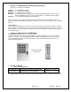
Step 3: Adding or Changing User Codes. User codes may be 1 to 6 digits in length. The 212iLM Mullion has to be in programming mode to add or change users Enter Programming Mode: 99# (Master code) * Next enter the user location. (2, 3, 4, etc.) followed by the # key. Now enter the new code followed by the * key (Yellow LED flashes rapidly). Repeat the new code followed by the * key (Yellow LED flashes slowly). If the change was successful, the yellow LED will still be flashing slowly.
Step 5: Changing the 212iLM Mullion Feedback Options. The 212iLM Mullion has two keypress feedback options that you may choose from. One is an audio feed back. This will activate the on board sounder every time that a key is pressed. The other is a visual feedback. This will flash the yellow LED on the front of the keypad every time that a key is pressed. These two options are used to verify when a key has been pressed. Both of these options may be used individually, together or not at all.
Step 7: Doorbell Option: When the doorbell feature is enabled there will be visual and audio keypress feedback for the bell button but when the feature is disabled there will be no keypress feedback. This doorbell feature has two modes of operation: timed and continuous. Timed will allow programming of the output for a specified number of seconds with a single short press. The doorbell is set for continuous by default and output bell sounds for as long as the button is pressed.
To enable/disable keypad dimming: If keypad dimming option is set to zero, then the keypad will maintain full illumination at all times. This option is enabled by default. Enter Programming Mode: 99# (Master code) * Next press Command number 30 followed by the # key. Next press "4" for the dimming option followed by the # key. Next press "0" to Disable or "1" to Enable the keypad dimming option followed by the # key. Next press the * key (Yellow LED flashes rapidly).
Programming Options Chart If the pre-programmed default values must be changed or additional functions are desired, the following options may be programmed. • Enter programming mode Press: 99 # (master code)* The master default code is 1234 and the 212iLM must be in programming to make any changes.
Section 6: Trouble Shooting. Refer to this section if the 212iLM Mullion is not responding correctly to the operation outlined in this instruction manual. The 212iLM Mullion has been designed to operate with 12-24 Volts AC or DC. Verify that the voltage powering this keypad is within these parameters. Situation 1: Reason: Solution: LED's are slowly cycling from right to left and the Backlighting is off. The 212iLM Mullion has been designed to monitor for low voltage.
International Electronics Incorporated (IEI) warrants its products to be free from defects in material and workmanship, when they have been installed in accordance with the manufacturer’s instructions, and have not been modified or tampered with. IEI does not assume any responsibility for damage or injury to person or property due to improper care, storage handling, abuse, misuse, normal wear and tear, or an act of God.
NOTES: IEI suggests that you make a record of your installation for future reference. Page 16 of 17 6051344 Rev. 1.
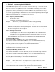
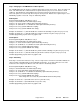
1 7/16” Diameter of the mounting holes is: 11/64 Diameter of the wiring holes is: 7/8 6 1/4” 3 3/8” This product is designed as a surface mountable product. The access hole for the wires is determined by the amount of wires that will run through the mounting surface. 1 7/16” Page 17 of 17 6051344 Rev. 1.