
Instruction Manual

6051344 Rev. 1.0
Page 2 of 17
q Section 1: Unpacking and checking the packing list
Open the box, and inside you will find:
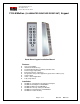
Keypad: (1) 212iLM Mullion keypad
Harnesses: (1) 8 Conductor wire harness
Wrenches: (1) Standard 5/64 allen wrench
Hardware: (1) Hardware Pack containing: (2) 8 x1¼” Panhead Slotted Machine Screw; (2) 8 x 1¼”
Round Head Wood Screw; (2) 6-8 x ¾” Plastic Anchor, (1) 212iLM mounting template.
Literature: (1) 212 Standalone Mullion Instruction Manual
Please check the contents of this package and verify all components in the packing list are present.
Taking this inventory will familiarize you with the components as well as ensure that you have a complete
parts list.
Tools required:
You will need a drill, drill bits1/8, 3/16 & 5/16 (for the plastic anchors), wire strippers, regular & small flat
blade screwdrivers, a marking pen or pencil, some heat shrinkable tubing (for the wire splices), a ruler or
measuring tape, silicone to seal any holes and possibly some electrical tape to hold the wires together or
the template in place.
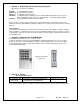
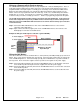
q Section 2: Mounting the 212iLM Mullion
212iLM Mullion Dimensions: 6 ½”L x 1 ¾”W x 1 1/8”D
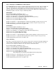
Select the appropriate location for the 212iLM Mullion. Mounting height is the same for an electrical
switch, 48" on center. The 212iLM Mullion should be Surface Mounted with a 1/4” hole for the wires
centered approximately 5/8 of an inch underneath the center of bottom mounting hole (refer to the
included mounting template).
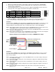
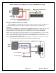
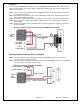
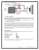
q Section 3: Wiring
Electrical Specifications:
Operating Voltages: Max Current Draw @ allowed voltages: Temperature Tolerance:
12-24V-AC/DC only
for input voltage.
53mA@12V, 72mA@24V; 94mA@12VAC,
103mA@16VAC, 108mA@24VAC
Standard, -20° to 130°F.
*Tech note- Although the 212iLM will work with AC or DC voltage, it is recommended to use a filtered
and regulated power supply for it’s ability to maintain voltage and reduce the possibility of voltage spikes.
Suggested mounting
height is 48”