
Instruction Manual

6051344 Rev. 1.0
Page 3 of 17
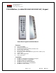
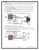
1. Attach the 8-conductor wire harness to the plug in connector on the back of the 212iLM Mullion.
2. Next you will need to attach the relay wires (white/yellow, blue, and brown) to the wire run that is
connected to the locking device.
3. The Red and Black wires are connected to the power supply last, BEFORE the power is turned on.
Connect positive of the supply to the Red wire and negative to the Black wire.
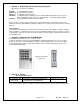
212iLM Mullion: Wire Colors and Designations:
Pin Wire Color Signal Name Pin Wire Color Signal Name
1 Red V in(+) 5 Blue Main Relay Common
2 Black V in(-) 6 Brown Main Relay NO
3 White/Black REX 7 White Bell Relay Contact (A)
4 White/Yellow Main Relay NC 8 White Bell Relay Contact (B)
Wiring to a Magnetic Lock: (see below)
The 212iLM Mullion is equipped with a Form C, Dry contact relay. This means that there is no
voltage running through the relay (until you supply the common leg of the relay with voltage).
Situation 1:
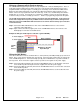
If you are using a common power supply with the 212iLM Mullion and the Magnetic Lock, (that is to say if
you have only one power supply for both the 212iLM Mullion and the lock device), you need to run
voltage through the common (blue) wire on the 8 conductor wire harness of the 212iLM Mullion
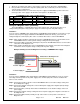
Step 1: Splice together the Blue (common) wire from the 212iLM Mullion harness to the Red wire on the
212iLM Mullion harness and to positive voltage coming from the power supply.
Step 2: Connect the White /Yellow wire (normally closed) from the 212iLM Mullion harness to the Positive
connection on the Magnetic Lock.
Step 3: Splice together the Black wire on the 212iLM Mullion to the Negative connection on the Magnetic
Lock harness and to negative voltage coming from the power supply.
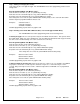
Example of Wiring to a Electro-Magnetic Lock Using a COMMON Power Supply:
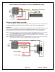
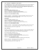
Situation 2:
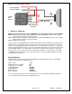
If you are using a separate power supply with the 212iLM Mullion and the Magnetic Lock, you need to
run voltage from the positive of the power supply to the common (blue) wire on the 8 conductor wire
harness of the 212iLM.
Step 1: Connect the Positive (red) wire on the 212iLM Mullion harness to Positive voltage coming from
the 212iLM power supply.
Step 2: Connect the Negative voltage wire on the 212iLM power supply to the Negative (black) voltage
wire on the 212iLM
Step 3: Connect the Blue (common) wire from the 212iLM harness to the Positive voltage on the lock
power supply
Step 4: Connect the Negative voltage coming from the lock power supply to the Negative connection on
the Magnetic lock.
Step 5: Connect the White/Yellow (normally closed) on the harness to the positive connection on
Magnetic Lock.
Blue =Common
To Power Supply V+
To Power Supply V-
White/Yellow = Normally Closed
Red
Black
1----
3----
5----
7----
----2
----4
----6
----8
_
+
212iLM
Wire
Harness