
Instruction Manual

6051344 Rev. 1.0
Page 7 of 17
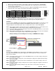
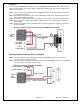
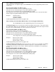
Example of wiring to a Bell or Speaker:
q Section 4: Power Up
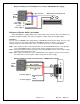
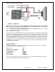
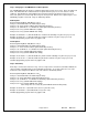
Making the Power Connections: (The 212iLM Mullion is powered with 12-24 Volts AC or DC ONLY)
Step 1: Connect the Red (positive voltage input) wire from the 212iLM Mullion harness to the positive
voltage output connection on the power supply.
Step 2: Connect the Black (Negative voltage input) wire from the 212iLM Mullion harness to the negative
voltage output connection on the power supply.
Step 3: Plug in the power supply.
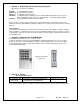
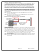
Upon power up, the 212iLM Mullion will cycle through the LED's from left to right twice to indicate proper
keypad operation. (If the LED's continue to flash, refer to the trouble shooting section of this manual on
page 14). The backlighting will now be on and will dim 15 seconds after the last keypress or 5 seconds
after the programming mode has been exited. The red LED should now be on. Perform the Self-Test by
pressing 7890#123456*. The LED’s will cycle from Green to Yellow to Red and then the sounder will
beep three times. Press 1234* and the main relay should energize for 5 seconds and the green LED
should light for the time the relay is open. After the relay closes, the green LED should turn off and the
red LED should come back on.
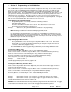
System Defaults:
The Door-Gard Keypad is designed for easy installation in a minimum amount of time. The following
default values have been factory programmed.
Master Code 1234
Audible Key Press Feedback On
Visual Key Press Feedback On
Keypad illumination Enabled
Keypad Dimming Enabled
Door bell select Enabled
Door bell duration Continuous
If it is necessary to change any of these defaults, please refer to the Programming Options Chart after
you have familiarized yourself with the programming section.
To Power Supply V+
To Power Supply V-
White (A) Common
Connection
White (B) Normally
Open Connection
Red
Black
_
+
+
212iLM
Wire
Harness