Slide Gate Operators Installation and Maintenance Manual Dorene Gate Openers DR 3020 DR 3020HX DRT 3520
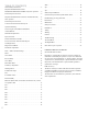
Table of Contents JS10. . . . . . . . . . . . . . . . . . . . . . . . . . . . . . . . . . . . . . . . . . . . . . 18 Important Installation Instructions DS4020/DS 4020H/DS & 4020HX (only) Gate operation. . . . . 6 Jp4. . . . . . . . . . . . . . . . . . . . . . . . . . . . . . . . . . . . . . . . . . . . . . . 18 General Safety Instructions. . . . . . . . . . . . . . . . . . . . . . . . . .
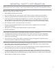
General Safety Information Read through the installation instructions completely before beginning installation, and then perform them in the order given IMPORTANT SAFETY INSTRUCTIONS Warning: To reduce the risk of injury or death 1. Read and follow all instruction carefully. 2. Never let children operate or play with gate controls. Keep the remote control away from children. 3. Always keep people and objects away from the gate. No one should cross the path of a moving gate. 4.
Install the gate operator only when: 1. The operator is appropriate for the construction of the gate and the usage class of the gate. 2. All openings of a horizontal slide gate are guarded or screened from the bottom of the gate to a 3. Minimum of 4’ (1.2m) above the ground to prevent a 2.25” (57.15mm) diameter sphere from passing through the openings anywhere in the gate, and in that portion of the adjacent fence that the gate covers in the open position. 4.
Gate operator Usage Class Horizontal Slide Swing Vehicular I and II A B1, B2, or D A or C A, B1, C or D Vehicular III A, B1, or B2 A, B1, B2, D or E A, B1 or C A, B1, C, D or E Vehicular IV A, B1, B2, or D A, B1, B2, D or E A, B1, C or D A, B1, C, D or E Note: The same type of device shall not be utilized for both the primary and the secondary entrapment protection means.
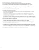
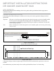
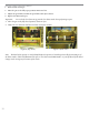
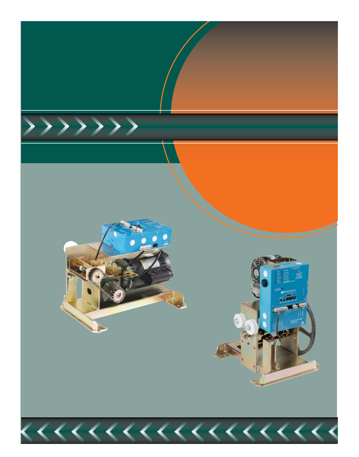
Important Installation Instructions Dr 3020/DR 3020HX/DRT 3520 Gate operation The gate must roll freely with no binding of the wheel, guides, and/or gate hardware before any operator is connected to the gate. Pad and Operator Location Position the pad as indicated in Figure #1. Failure to do so may cause erratic operation resulting in reduced operator life.
Concrete pad Construction and Layout The gate must roll freely with no binding of the wheel, guides, and/or gate hardware before any operator is connected to the gate.
Concrete pad Construction and Layout The gate must roll freely with no binding of the wheel, guides, and/or gate hardware before any operator is connected to the gate.
Mechanical hook up (Front mount) Position the pad as indicated in Figure #1. Failure to do so may cause erratic operation resulting in reduced operator life. 1. Clamp both chain bolt brackets to the gate as in Figure 2, with the hole in each of the brackets lining up with the operator idler sprocket, vertically and horizontally. Weld in place Important: Failure to line up brackets properly will result in premature idler and guide wear and may cause the chain to jump off the sprocket. 2.
Initial Limit Adjustment 1. Remove limit nut keeper 2. Move the gate to the fully open position, minus one foot 3. Adjust the open limit nut until the open limit switch just activates. 4. Replace the limit nut keeper. Important: Do not let the close limit nut go past the close limit switch when performing step #5. 5. Move the gate to the fully closed position, minus one foot 6. Adjust the close limit nut until the close limit switch just activates.
Dorene DGC2000 Controller 11
Power Connection / Electrical Hookup Important: Turn power OFF at the breaker before making any connections or adjustments. Note: Port 1, 2, 11 and 12 are not to used. They are empty ports. The operator should be on a separate line with a 15 AMP breaker. Supply voltage must be within 10% of the operator rating under load conditions.
Clutch Adjustment Important: Always turn power off before making any adjustment. 1. Remove the two set screws in the clutch adjuster nut. 2. Using a 1 ¼” Open-end wrench (available at the factory) tighten the clutch adjuster nut until proper tension is achieved. (See Note below) Try just a ¼ turn at a time and then test. DO NOT USE A PIPE WRENCH OR CHANNEL LOCKS TO ADJUST THE CLUTCH!.
Close Delay If the close time is switched into the circuit, this set of switches adjusts the length of time the gate stays open before closing automatically. For example, if you want 45 second you would turn on 32+8+4+1=45 as illustrated below in figure 12. 32 16 8 4 2 1 ON OFF Figure 12 Motor Run Timer This timer should be set at least 10 seconds or longer than the normal operating time, and will stop the gate if for some reason the motor runs longer than the switch setting.
To Hold Gate Open Wire switch to stop prior to full open to close reverse switch and press transmitter to restart. JP-3 Anti-tailgate feature. See Figure #6 on page 11 Led enable switch The two rows of LED’s, located in the upper left hand corner of the DGC 3000, Functions for thirty minutes from power-up and turns off automatically to save power. To verify the LED’s are enabled, activate a limit switch momentarily.
Blue Box format All Commands are dry contact, except JS4 & JS8 JS1 Open / Common / Closed. — Dry Contact Command: For Open & Closed gate function, Telephone Entry, Digital Key Pad, Postal Box, etc... JS2 Limit Switches — Pre-wired, normally a closed circuit JS3 Stop / Common / Pulse, Stop / Common — Normally a closed circuit, for a stop button on 3 button switch (remove jumper wire on JS7 if JS3 is used) Pulse/Common for use when “close timer is off to open & close gate with transmitter.
JS8 +Alarm / –Alarm / Spare — For external alarm prior to gate moving either open or closing. JS9 Loop Detector-Photo Eye / Common / Loop Detector-Photo Eye — Normally open circuit to connect safety loop and/or photo eyes to operator. JS10 Open / Common / Pulse — Jumper wire must be used on open / common, it is ready for ready for transmitter / receiver with automatic timing closing. Common / Pulse for use with transmitter open a transmitter closing.
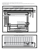
Synchronous OPEN/CLOSE OPERATION DGC 2000 JS9 JS1 JS3 JS6 JS9 OPEN COMMON CLOSE STOP COMMON PULSE GATE EDGE COMMON GATE EDGE VEHICLE LOOP/PHOTO EYE COMMON VEHICLE LOOP/PHOTO EYE STOP COMMON PULSE JS6 VEHICLE LOOP/PHOTO EYE COMMON VEHICLE LOOP/PHOTO EYE JS3 RIGHT GATE EDGE COMMON GATE EDGE JS1 OPEN COMMON CLOSE LEFT only if needed 1. Controllers must be operated from same 110v line. 2.
Synchronous OPEN/CLOSE OPERATION DGC 2000 LEFT RIGHT N.C. SWITCH BLACK RED STOP WIRES RED BLACK RED STOP COMMON PULSE JS7 STOP COMMON PULSE JS7 BLACK COMMON WIRES 1. Controllers must be operated from same 110v line. 2. Synchronous* Open/Close operation ins obtained by installing two twisted pair cables between the JS1 Open/Common and Close/Common connectors of two DGC 2000 controllers. 3. Connection required only with the Gate Edge or other Safety Device.
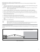
Double Swing gate loop placement 4 Foot General Rule FREE EXIT LOOP - Shortest leg on loop is minimum of 4 ft. INSIDE - 4 ft. space between loops - 4ft. away from edge of gate SAFETY LOOP 4 ft. min. SHADOW/CENTER LOOP 4 ft. 4 ft. SAFETY LOOP OUTSIDE 2 ft. VEHICLE Figure 15 20 4 ft. min.
Final Check 1. Turn power ON at breaker and recheck all functions, including all safety functions. 2. If any adjustments are necessary, make those adjustments and re-test for proper operation. 3. Gate is now ready for normal operation. Important: The gate operator installation is not complete unless the warning signs are installed on the gate. Maintenance 1. Severe or excessive usage requires more frequent checks. 2. All safety functions should be verified at least once every three months. 3.
Troubleshooting To trouble shoot the gate operator it is important to understand how the LED’s function work. Note: The power LED functions all the time that power get to the DGC 2000 Controller box. The LED’s function for thirty minutes from power-up and go off automatically to save power. To verify that the LED’s are enabled, activate a limit switch momentarily. If the corresponding LED does not light, press the LED enable switch, located below the LED’s to enable them for another thirty minutes.
www.gateopeners.