
User guide

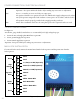

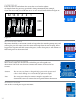
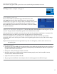
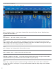

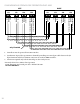
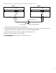

Table Of Contents
- IMPORTANT SAFETY INSTRUCTIONS
- Important Installation Instructions Ds4020/Ds 4020H/Ds & 4020HX (only)Gate operation
- Pad and Operator Location
- Important Installation Instructions for the DST 4520 0nly
- Gate operation
- Pad and Operator Location
- Concrete Pad Construction and Layout
- Operator Mounting
- Universal gate arm Installation Guidelines
- Arm Installation
- Initial Limit Adjustment
- Pipe Connection
- Dorene DGC2000 Controller
- Power Connection / Electrical Hookup115 Volt Single PhaseSee figure 10
- Mag-Lock installationIf a 115 volt lock is used, connect the neutral wire from the lock to port #7 and the power wire from thelock to port #6 
- Final Limit Adjustment
- DGC – 2000 Controller Settings 
- Hand
- Close Timer
- Reverse Delay 
- Close Delay 
- Motor Run Timer 
- Sensitivity Adjustment 
- Warning Alarm 
- To Hold Gate Open
- JP-3 
- Led enable switch 
- Final Assembly
- Blue Box formatAll Commands are dry contact, except JS4 & JS8
- JS1
- JS2
- JS3
- JS4
- JS5
- JS6
- JS7
- JS8
- JS9
- JS10
- Jp3
- Jp4
- Shadow loop Installation
- SychronousOPEN/CLOSE OPERATIONDGC 2000
- Double Swing gate loop placement
- 
- Final Check
- Maintenance
- Safety Accessories
- Installation
- Testing
- Warning
- Caution
- Troubleshooting
- The left LED’S
- The Right LED’s
- Gate will not open or operate

13
CLUTCH ADJUSTMENT
Important: Always turn power o before making any adjustment.
Remove the two set screws in the clutch adjuster nut.1.
Using a 1 ¼” Open-end wrench (available at the factory) tighten the clutch adjuster nut until proper tension 2.
is achieved. (See Note below) Try just a ¼ turn at a time and then test. DO NOT USE A PIPE WRENCH OR
CHANNEL LOCKS TO ADJUST THE CLUTCH!.
Important: Do not over tighten the clutch! Gear damage may result voiding the warranty!
Note: e clutch must be suciently tight so that it does not slip in normal operation and so that the motor
and the current sensor “feel” a load when the gate is obstructed.
Aer the clutch is properly adjusted, with power OFF, tighten the two set screws in the clutch adjuster nut.3.
FINAL LIMIT ADJUSTMENT
It is possible that a nal adjustment may be required for the arm to stop exactly as desired. In the open position,
the swing arms and the pipe arm should be doubled on the top of each other. On CLOSE the motor should
turn o before the arm hits the stop so that it coasts to the stop. If the operation is not as described, adjust the
position of the limit collar to correct the error.
DGC – 2000 CONTROLLER SETTINGS HAND
is switch changes the direction the motor runs to open the gate, le or right
CLOSE TIMER
is switch is used to activate (on) or deactivate (o) the automatic close timer. e gate will
close aer a specied time as set under Close Delay if this switch is ON unless the gate is
being held open by an accessory.
Brake Delay (for slide gates only)
is set of switches determines the length of time between the motor turning o and the
electronic brake coming on. All switches should be ON except for a gate on an incline.
REVERSE DELAY
is set of switches is to prevent instant reversal of the motor to reduce operator/gate stress
and to prevent operator malfunction. Note: Never put all of these switches in the OFF position as
operator damage may result.