PRINTER’S INSTRUCTIONS: INSTR,INSTL,AE-500 - LINEAR P/N: 220793 G - INK: BLACK - MATERIAL: 20 LB. MEAD BOND - SIZE: 8.500” X 11.000” - SCALE: 1-1 - FOLDING: ALBUM-FOLD - BINDING: SADDLE-STITCH AE-500 Telephone Entry & Access Control System Installation Instructions USA & Canada (800) 421-1587 & (800) 392-0123 (760) 438-7000 - Toll Free FAX (800) 468-1340 www.linearcorp.
Contents Introduction ........................................ 2 Operation............................................ 2 Hardware Features ............................. 2 Software Highlights ............................ 2 Remote Keypads ................................. 2 Feature Overview ................................ 3 Component Locations ......................... 4 Wiring Diagram ................................... 5 Important Mounting Requirements ...... 6 Entry System Mounting.......................
Feature Overview Database Overview Relay Outputs Programming the AE-500 involves entering installation information into the system’s memory. The system uses this information as a reference “database” to control the operation of the system. Two 3-amp dry contact relay outputs are provided to activate access devices, such as door strikes, magnetic locks, automatic doors, barrier gates, and automatic sliding gates.
Component Locations OPTIONAL CAMERA MICROPHONE DISPLAY OPTIONAL POSTAL LOCK CABINET LOCK KEYPAD SPEAKER KEYPAD LIGHTING MAIN POWER SWITCH EARTH GROUND STUD POWER INDICATOR RECEIVER VIDEO OUT TEST POINTS CONNECTOR RECEIVER RANGE KNOB CAMERA CONNECTOR ANTENNA CONNECTOR INSTALLATION NOTE: FOR EASY WIRING, THE UNIT'S GREEN TERMINAL BLOCKS CAN BE UN-PLUGGED FROM THE CIRCUIT BOARD MICROPHONE CONNECTOR DISPLAY MICROPHONE CAMERA MOUNTING LOCATION POWER TERMINALS POSTAL LOCK MOUNTING PLATE KEYPAD TE
Wiring Diagram THIS WIRING EXAMPLE SHOWS PRIMARY ACCESS WITH A DOOR STRIKE ON RELAY CHANNEL "A" AND SECONDARY ACCESS WITH A GATE OPERATOR ON RELAY CHANNEL "B" CASE GROUND STUD 16 VAC 20 VA TRANSFORMER 12 VOLT BATTERY AE-500 NOTE: OPTIONAL BACKUP BATTERY WILL REQUIRE AN EXTERNAL CHARGER PWR GND DAT1 DAT0 DVAL PCLK PWR GND REMOTE DAT1 KEYPAD DAT0 REMOTE KEYPAD DVAL FOR GATE ENTRY PCLK KEYPAD TERMINALS RELAY RATING: 3 AMPS @ 30 VOLTS AC/DC MAXIMUM ELECTRIC DOOR STRIKE RELAY "A" DOOR STRIKE POWER SUPPL
Important Mounting Requirements The AE-500 Telephone Entry System can be installed for public or private use. The mounting requirements will vary depending on the installation. Review the following information before beginning the installation. Mounting Environment Consider the environmental factors at the desired mounting location. The AE-500 is designed for direct outdoor installations, however, it is preferable to protect the unit from extreme exposure to sun, driving rain, or snow whenever possible.
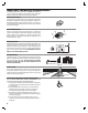
Entry System Mounting The AE-500 cabinet is designed to be mounted three ways: • The unit can be mounted directly to a wall or flat surface. • The unit can be mounted recessed into a wall. • The unit can be mounted on a standard goose-neck pedestal. Choose a well lit location near the controlled opening. Wiring access for power, telephone, earth ground, and control output must be available to the mounting location.
Entry System Mounting (Continued) Recessed Mounting The cabinet can be mounted recessed using the accessory trim-ring (P/N ACP00908). The trim-ring mounts in the wall and the cabinet attaches to the trim-ring. 1. Identify the location of any studs in the wall. 2. Cut a 13” high by 11” wide rectangular hole between studs at the mounting location. 3. Install any additional mounting material required to provide surfaces inside the wall 11” apart for attaching the trim-ring. 4.
Relay Output Wiring Door or Pedestrian Gate Control 1. Install a low voltage electric door strike or magnetic lock as a locking device for the door or pedestrian gate. 2. Install the power supply or transformer for the locking device. DO NOT POWER THE AE-500 FROM THIS POWER SUPPLY. 3. Connect one wire from the power supply to one wire from the locking device. 4. Route two wires between the locking device and the AE-500. Connect one wire to the remaining wire of the locking device.
Power, Battery, & Ground Wiring Power Wiring ✦ NOTE: DO NOT APPLY POWER UNTIL THE INSTALLATION IS COMPLETE.TURN MASTER POWER SWITCH OFF BEFORE WIRING. 1. Route two wires between the AE-500 and the power transformer. • For power wire runs up to 100 feet, use 18 AWG, THHN 600-volt insulated wire. • For power wire runs up to 200 feet, use 16 AWG, THHN 600-volt insulated wire. 2. Connect the wires to the transformer. Connect the other end of the wires to the AE-500 AC1 & AC2 terminals.
Telephone Wiring For telephone entry and programming, the AE-500 connects to a standard telephone line. Important Telephone Wiring Tips • DO NOT ROUTE TELEPHONE AND AC WIRING INSIDE THE SAME CONDUIT. Route all telephone wires inside a dedicated conduit that is at least six inches away from any AC line wiring. • All telephone wiring must be made on the “building” side of the telephone company’s demarcation device (the terminal block where the telephone line connects to the building).
Optional Postal Lock 2 REMOVE PLATE 1 REMOVE LOCKNUTS A postal lock can be installed in the AE-500 Entry System to provide keyed access for the postal service. The AE-500 case is designed to accept a U.S. Postal Service postal lock. When the postal lock is engaged, Relay Channel “A” will activate. Postal Lock Installation 1. Remove the four locknuts that retain the postal lock switch plate (above the keypad on the AE-500 faceplate). 2. Remove the switch plate from the four studs. 3.
Programming with a Computer The AE-500’s built-in programming interface can be accessed on-site (using a separate telephone line) or off-site using a computer with a modem and Internet Explorer browser (with Sun Java installed). The AE-500 can be programmed using the local keypad or with a telephone, but computer programming is the easiest method. Navigating through the AE-500’s programming “pages” is similar to browsing through your favorite web site’s pages.
Programming Over the Telephone The system can be programmed using a TouchTone™ telephone. The telephone’s keypad will act similar to the AE-500’s local keypad. 1. CALL THE SYSTEM Connecting with a Telephone 2. WAIT FOR THE TONE TO FINISH 1. Place a call to the telephone number of the line that AE-500 is connected to. 2. The AE-500 will answer and sound a tone for about ½ second. 3. After the tone, enter the master password, then press # (factory setting is 123456).
Programming Reference Factory Settings PROGRAMMING CONTROL PPN # PPN 01 PPN 02 PPN 03 PPN 04 PPN 31 PPN 31 PPN 44 USAGE KEYSTROKES ENTER PROGRAMMING FROM LOCAL KEYPAD . . . . . . . . Press 0 and 2 then MASTER PASSWORD ENTER PROGRAMMING FROM TELEPHONE . . . .Call, wait for tone then enter MASTER PASSWORD ESCAPE/CANCEL . . . . . . . . . . . . . . . . . . . . . . . . . . . . . . . . . . . . . . . . . . . . . . . . . . . . . . . . . . . . * EXIT PROGRAMMING. . . . . . . . . . . . . . . . . . . . . . . . . .
Setting Up Multiple Units The system supports up to seven AE-500s connected to the same telephone line. Some telephone systems may only support up to four units on the same telephone line. In multiple-unit installations each AE-500 must be assigned a unique unit number before programming. The unit number allows connecting to a specific unit when calling for programming. One unit must be assigned as Unit #1. ✦ NOTE: If this is the only unit used in the installation, leave the factory setting at one.
Resident Data Programming Up to 250 resident names and telephone numbers can be set. Each resident entry is assigned a directory number. The directory numbers are the numbers visitors enter to have the system call the residents. ✦ NOTE: When entering resident names, programming the AE-500 from a computer is the preferred method. Refer to the “Programming from the Local Keypad” section of these instructions for details on alphanumeric entry from the keypad.
Entry Code Programming An entry code is a number entered at the AE-500 keypad or remote keypad to request access. Up to 500 entry codes can be set. Entry codes can be from two to six digits in length (all will be the same length). Entry codes can be programmed for timed or toggle operation. Timed relays activate for a programmed length of time. Toggle relays latch on until the next time a toggle entry code is entered, then the relay unlatches.
Wireless Transmitter Programming Up to 500 wireless transmitters can be used with the system. Transmitters can be ordered in pre-programmed blocks of sequential ID codes. Up to 16 blocks of transmitters can be used. Transmitter blocks can be ordered with a Facility Code of 1-15 for block identification if desired. Using Facility Codes is optional. For security, an individual transmitter can be deactivated in case it is lost or stolen.
Wireless Transmitter Programming (Continued) Delete single Enrolled Transmitter Delete a single enrolled transmitter from the system. 1. If not alreay in Programming Mode, connect by telephone or use the local keypad. Enter the master password and access programming. 2. Press 3. Enter the transmitter facility code. 4. Press 5. Enter the transmitter ID number of the transmitter. 6. Press 7. Exit Programming Mode if all programming is complete.
System Options (Continued) Sensing Input Function The Sensing Input (DS-A terminal) can be set for Door Sense or Access Inhibit. • When the Sensing Input is used for “Door Sense”, the input connects to a switch that detects if the access portal is open or closed. Monitoring the portal status permits use of the alternate functions of Relay Channel “B” (PPN #53).
System Options (Continued) Welcome Display Text The AE-500 display will show a visitor a welcome message alternating with instructions on how to call a resident. The welcome message can be customized to suit the installation. ✦ NOTE: When changing the welcome display, programming the AE-500 from a computer is the preferred method. Refer to the “Programming from the Local Keypad” section of these instructions for details on alphanumeric entry from the keypad. 1.
System Options (Continued) Maximum Visitor Talk Time Visitors will converse with residents over the telephone until the resident grants or denies access. If the resident responds to the visitor’s request by pressing their telephone keys the system will hang up and release the telephone line. If for some reason the resident does not press the telephone keys or does not hang up, the system will automatically disconnect the visitor after 60 seconds.
System Utilities Several utility commands are available for the system. Utilities can be used to clear memory, display system information, and control the relays. DISPLAY UNIT NUMBER Display Unit Number In multi-unit installations the unit number of each AE-500 can be displayed. 1. If not already in Programming Mode, use the local keypad to enter the master password and access programming. 2. Press 3. The display will show the unit number for three seconds. 4.
System Adjustments The factory settings are sufficient for most installations. The system can be adjusted to customize the installation. System Tone Adjustment The sound level of the tones that the system produces can be adjusted. 1. Locate the TONE VOLUME adjustment on the main circuit board. 2. Press keys on the keypad while adjusting the TONE VOLUME until the tones are at the desired level. Turn the adjustment clockwise for more volume, counterclockwise for less volume.
AE-500 Operation Requesting Access with an Entry Code • Residents/authorized personnel have up to 40 seconds to key in their entry code. • Up to eight seconds are allowed between each keystroke. • All digits of the entry code must be entered. Example: If the entry code length is set for four digits, and the code is 0042, the user must enter “0 0 4 2”. • If the wrong key is pressed, pressing the key will reset the keypad. The correct code can then be re-entered.
Specifications MECHANICAL Case dimensions: ELECTRICAL Voltage: Current: Backup Battery: Outputs: Troubleshooting System completely dead 10-3/4” W x 12-3/4” H x 3-1/2” D 12-24 Volts AC/DC 500 mA DC typical, 750 mA DC maximum Externally charged 12 Volt DC source Relay Channels A & B Form “C” 3 Amps @ 30 Volts maximum Inputs: One sensing input Two exit request inputs RADIO Frequency: RF 3db Bandwidth: Sensitivity: Encoding: ENVIRONMENTAL Temperature: Humidity: SYSTEM Relay On Time: Interkey Time: Code Entr
Linear Limited Warranty FCC Notice This Linear product is warranted against defects in material and workmanship for twenty-four (24) months. The Warranty Expiration Date is labeled on the product. This warranty extends only to wholesale customers who buy direct from Linear or through Linear’s normal distribution channels. Linear does not warrant this product to consumers. Consumers should inquire from their selling dealer as to the nature of the dealer’s warranty, if any.