PRINTERS INSTRUCTIONS: INSTR,INSTL,AK-11,ACCESS - LINEAR P/N: 227975 A - INK: BLACK - MATERIAL: 20 LB. MEAD BOND - SIZE: 8.500” X 11.000” - SCALE: 1-1 - FOLDING: ALBUM-FOLD - BINDING: SADDLE-STITCH AK-11 Digital Keyless Entry System Installation and Programming Instructions (760) 438-7000 USA & Canada (800) 421-1587 & (800) 392-0123 Toll Free FAX (800) 468-1340 www.linearcorp.
CONTENTS INTRODUCTION . . . . . . . . SPECIFICATIONS . . . . . . . FEATURES . . . . . . . . . . . COMPONENT LOCATIONS . . . WIRING DIAGRAM . . . . . . INSTALLATION . . . . . . . . FACTORY DEFAULTS . . . . . . BASIC PROGRAMMING . . . . PROGRAMMING OPTIONS . . AK-11 OPERATION . . . . . . MANAGER’S ENTRY CODE LOG LINEAR LIMITED WARRANTY . FCC NOTICE . . . . . . . . . . SPECIFICATIONS . . . . . . . . . . . . . . . . . . . . . . . . . . . . . . . . . . . . . . . . . . . . . . . . . . . . . . . . . . . . . .
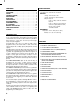
COMPONENT LOCATIONS RED/GREEN POWER/ACCESS INDICATOR YELLOW "LOCKOUT" INDICATOR JUMPER JP2 RESETS MASTER CODE TERMINAL BLOCK J3 OUTPUTS NIGHT LIGHT TACTILE KEYPAD TERMINAL BLOCK J4 POWER AND INPUTS JUMPER JP1 REMOVE TO REDUCE BEEPER SOUND KEYLOCK Figure 1. Component Locations WIRING DIAGRAM TYPICAL GATE INSTALLATION WIRING TYPICAL DOOR INSTALLATION WIRING AK-11 AK-11 J3 J3 N.O. 1 RELAY #1 N.O. 1 COMMON 2 RELAY #1 N.C. 3 J4 N.C.
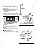
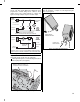
INSTALLATION To avoid damage to the unit from static discharges, connect the EARTH GROUND terminal to a good earth grounding point. Suggested wiring size is 18 AWG for earth ground and power (up to 500 feet of 18 AWG wire can be run for power, use larger wire for longer runs). Use 22 AWG or larger (depending on the load) for all other connections.
Gate Control Door Control Route four wires between the gate and the keypad (two for power, two for control). Connect the gate operator’s auxiliary or radio power output terminals to the keypads POWER input terminals (observe wiring polarity). Connect the gate operator’s OPEN terminals to the keypad’s Relay #1 COMMON & N.O. terminals. NOTE: For operator wiring specifics, refer to the gate operator’s wiring diagram.
FACTORY DEFAULTS Setting Entry Code Length MASTER PROGRAMMING CODE . . . . . . . . . . . . . . . . . . . . 123456 ENTRY CODE LENGTH . . . . . . . . . . . . . . . . . . . . . . . . . . 4 DIGITS REQUEST-TO-ENTER OUTPUT . . . . . . . . . . . . . . . . . . RELAY #1 ALARM SHUNT OUTPUT . . . . . . . . . . . . . . . . . . . . . . . . DISABLED FORCED ENTRY OUTPUT . . . . . . . . . . . . . . . . . . . . . OUTPUT #3 DOOR AJAR OUTPUT . . . . . . . . . . . . . . . . . . . . . . . . . OUTPUT #4 RELAY #1 ON TIME . . .
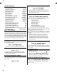
PROGRAMMING OPTIONS Select Door Sense or Inhibit Input Default: Door Sense The input on terminal block J4, terminal #3 can be programmed for DOOR SENSE or INHIBIT. Press: 1 0 # Input# Input = 1 for Inhibit, = 0 for Door Sense When programmed for DOOR SENSE, if an open condition on the input occurs before access is granted (with an entry code or with the request-to-enter input) a FORCED ENTRY output will occur.
Beep Sounds on Keystrokes Default: Yes Selects whether or not the keypad beeps as each key is pressed. Press: 4 0 # Sound # Sound = 1 for Yes = 0 for No Beep Sounds During Relay #1 Default: No Selects whether or not the keypad beeps during Relay #1 activation. Press: 4 1 # Sound # Sound = 1 for Yes = 0 for No Beep Sounds During Relay #2 Default: No Selects whether or not the keypad beeps during Relay #2 activation.
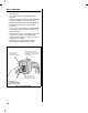
Solid State Outputs Locking Keypad The two solid state outputs (Output #3 & Output #4) can be programmed to activate during various conditions. These outputs can be used to activate indicators or sounders. See Figure 7 for wiring examples using the solid state outputs. After the installation is complete. Lock the keypad using the keylock (see Figure 9).
AK-11 OPERATION Users of the AK-11 have up to 40 seconds to key in their entry code. Up to eight seconds are allowed between each keystroke. All digits of the entry code must be entered. Example: If the code is 0042, the user must enter “0 0 4 2”. If the wrong key is pressed, pressing the key will reset the keypad. The correct code can then be re-entered. After a correct code is entered, the red LED will turn green and the programmed relay will activate for the programmed time.
MANAGER’S ENTRY CODE LOG NAME ADDRESS OR APARTMENT NUMBER ENTRY CODE RELAY NUMBER ◊ 1 Timed ◊ 1 Toggled ◊ 1 Timed ◊ 1 Toggled ◊ 1 Timed ◊ 1 Toggled ◊ 1 Timed ◊ 1 Toggled ◊ 1 Timed ◊ 1 Toggled ◊ 1 Timed ◊ 1 Toggled ◊ 1 Timed ◊ 1 Toggled ◊ 1 Timed ◊ 1 Toggled ◊ 1 Timed ◊ 1 Toggled ◊ 1 Timed ◊ 1 Toggled ◊ 1 Timed ◊ 1 Toggled ◊ 1 Timed ◊ 1 Toggled ◊ 1 Timed ◊ 1 Toggled ◊ 1 Timed ◊ 1 Toggled ◊ 1 Timed ◊ 1 Toggled ◊ 1 Timed ◊ 1 Toggled ◊ 1 Timed ◊ 1 Toggled ◊ 1 Timed ◊ 1 Toggled ◊ 1 Timed ◊ 1 Toggled ◊ 2 Tim
LINEAR LIMITED WARRANTY FCC NOTICE This Linear product is warranted against defects in material and workmanship for twenty-four (24) months. The Warranty Expiration Date is labeled on the product. This warranty extends only to wholesale customers who buy direct from Linear or through Linear’s normal distribution channels. Linear does not warrant this product to consumers. Consumers should inquire from their selling dealer as to the nature of the dealer’s warranty, if any.