PRINTER’S INSTRUCTIONS: INSTR,INSTL,AM3PLUS - LINEAR P/N: 227542 A - INK: BLACK - MATERIAL: 20 LB. MEAD BOND - SIZE: 8.500” X 11.000” - SCALE: 1-1 - FOLDING: ALBUM-FOLD - BINDING: SADDLE-STITCH AM3Plus Access Controller Installation Instructions (760) 438-7000 • FAX (760) 438-7043 USA & Canada (800) 421-1587 & (800) 392-0123 Toll Free FAX (800) 468-1340 www.linearcorp.
Contents Introduction . . . . . . . . . . . . . . . . . . . . . . . . . . . . . . . . . . . . . 2 Operation . . . . . . . . . . . . . . . . . . . . . . . . . . . . . . . . . . . . . . . 2 Programming and Cardholder Maintenance . . . . . . . . . . . . . . 2 Hardware Features . . . . . . . . . . . . . . . . . . . . . . . . . . . . . . . . 3 Software Highlights . . . . . . . . . . . . . . . . . . . . . . . . . . . . . . . 3 Feature Overview . . . . . . . . . . . . . . . . . . . . . . . . . . . . . . . . .
Hardware Features ✓ FOUR FORM “C” (N.O. & N.
Accessory Overview PBUS Accessories Several compatible accessories are available to connect to the two 6wire communications “PBUS” inputs. Up to six PBUS accessories can be used with each AM3Plus unit.
Component Locations STATUS/PROGRAM DISPLAY ARROW BUTTONS POWER INDICATOR STATUS INDICATORS AM3PLUS ACCESS CONTROLLER RELAY INDICATORS (4) RESET BUTTON ENTER BUTTON RELAY LATCH BUTTONS (4) AM-MIO INTERFACE CONNECTOR (HIDDEN) COM PORT CONNECTOR TELEPHONE LINE CONNECTOR TERMINAL BLOCKS POWER SWITCH 5
Wiring Diagram CHANNEL B RELAY RATING: 3 AMPS @ 30 VOLTS AC/DC MAXIMUM CHANNEL D EARTH REQUEST-TO-EXIT PBUS DOOR SENSE TAMPER COM. N.C. N.O. COM. N.C. N.O. GND. GND. RTE-A GND. RTE-B RTE-C GND. RTE-D DS-A GND. DS-B DS-C GND. DS-D PWR. GND. DAT1 DAT0 DVAL PCLK T1 POWER T2 AC-DC AC-DC TERMINALS 1-30 N.C. 1 2 3 4 5 6 7 8 9 10 11 12 13 14 15 16 17 18 19 20 21 22 23 24 25 26 27 28 29 30 PWR GND DAT1 DAT0 DVAL PCLK POWER INPUT 12-24 VOLTS AC OR DC 250 mA MIN.
Important Mounting Requirements The AM3Plus Access Control System can be installed for public or private use. The mounting requirements for remote keypads will vary depending on the installation. Review the following information before starting the installation. Mounting Environment Consider the environmental factors at the desired mounting location.
AM3Plus Mounting Standard Cabinet The AM3Plus cabinet is designed to be mounted directly to a wall or flat surface. Wiring access for power, telephone, earth ground, control output must be available at the mounting location. For easier wiring, choose a well lit location. Wiring access for remote accessory cables must also be available at the mounting location. 1. Flip the cabinet’s cover up to unlock the hinges and remove the cover from the case. 2.
Relay Output Wiring Any of the four relay outputs channels (A-D) can be used to control access devices on doors or gates. 1. Install a low voltage electric door strike or magnetic lock as a locking device for the door or pedestrian gate. 2. Install the power supply or transformer for the locking device. DO NOT POWER THE AM3Plus FROM THIS POWER SUPPLY. 3. Connect one wire from the power supply to one wire from the locking device. 4. Route two wires between the locking device and the AM3Plus.
Power, Battery, & Ground Wiring Power Wiring ✦ NOTE: DO NOT APPLY POWER UNTIL THE INSTALLATION IS COMPLETE. TURN MASTER POWER SWITCH OFF BEFORE WIRING. 1. Route two wires between the AM3Plus and the power transformer. • For power wire runs up to 100 feet, use 18 AWG, 600-volt insulated wire. • For power wire runs up to 200 feet, use 16 AWG, 600-volt insulated wire. 2. Connect the wires to the transformer. Connect the other end of the wires to the AM3Plus AC1 & AC2 terminals.
Telephone Wiring For programming, the AM3Plus connects to a standard telephone line. ✦ NOTE: The optional Model ACM-1 modem is required for telephone communications to the AM3Plus controller. AM3PLUS TELEPHONE LINE JACK Important Telephone Wiring Tips • DO NOT ROUTE TELEPHONE AND AC WIRING INSIDE THE SAME CONDUIT. Route all telephone wires inside a dedicated conduit that is at least six inches away from any AC line wiring.
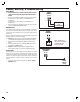
AM3PLUS READER TERMINALS PWR GND DAT0 DAT1 LED1 HOLD LED2 The two AM3Plus Wiegand inputs (READER A & B) can connect to a large variety of 26, 30, and 31-bit Wiegand output accessories. The Wiegand format is a common standard for access control equipment. A typical application would be to add swipe card or proximity readers to the system. ✦ NOTE: Depending on the Wiegand accessory used, the LED1, LED2, and HOLD connections may not be required. • LED1 output is switched to ground during non-access time.
Optional Network Connections Linear’s AM3Plus, AE1000Plus, & AE2000Plus Access Control Systems can be connected together in a network. A network will allow sharing programming and user information between the systems. Program each unit to a different network Node Address (see Page 16). ✦ IMPORTANT COMPATIBILITY NOTE: Linear’s previous access control Models AE-1000, AE-2000, & AM3 can be used in networks with the Models AE1000Plus, AE2000Plus, & AM3Plus only using AccessBase2000 software.
Optional Network Connections (Continued) Network Configuration for AccessBase2000 Programming If the system is going to be programmed using Linear’s AccessBase2000 software, units communicate with each other on the network through RS-485 cable connections. AccessBase2000 does not support unit-to-unit network communications through modems, only RS-485 cable. AccessBase2000 does support modem communications from the PC to the eight Node #1 “master” units on an AccessBase2000 network.
Optional Network Connections (Continued) RS-485 Network Wiring Network wiring conforms to 3-wire RS-485 electrical specifications. Units connected in the network can be wired using one unit as a “hub” or by wiring from one unit to the next in “daisy-chain” fashion. See the figures for wiring options. • Use Belden 9925 or Carol C0600 shielded cable or equivalent. Maximum wire run distance is 4000 feet. ✦ NOTE: Be sure to connect the cable’s shield to one of the GND terminals.
System Controls STATUS/PROGRAM DISPLAY Pushbuttons Refer to the figure for the location of each of the eight pushbuttons. • UP button adds one to the value on the STATUS/PROGRAM display. • DOWN button subtracts one from value on the STATUS/PROGRAM display. Press with the UP button for one second to enter Programming Mode. • ENTER button accepts the value on the STATUS/PROGRAM display during programming, clears an indication during the supervisory display.
System Diagnostics Several indicators on the AM3Plus are for monitoring the system during operation. When calling for technical assistance, Linear’s Technical Services Department may ask the installer to use these indicators to diagnose the system. Indicators 15 LED indicators are on the AM3Plus. Refer to the figure for the location of each indicator. • POWER lights when AC or DC power is present. • STATUS/PROGRAM DISPLAY shows supervisory and status conditions, also used for some local programming.
Specifications MECHANICAL Case dimensions: ELECTRICAL Voltage: Current: Backup Battery: Outputs: 11.5” W x 12.5” H x 3.
Linear Limited Warranty This Linear product is warranted against defects in material and workmanship for twenty-four (24) months. This warranty extends only to wholesale customers who buy direct from Linear or through Linear’s normal distribution channels. Linear does not warrant this product to consumers. Consumers should inquire from their selling dealer as to the nature of the dealer’s warranty, if any.
Copyright © 2007 Linear LLC 227542 A