
Instruction Manual
3
Note: If a shiny object, such as a chrome-plated item or
something with reflective tape, is within close proximity of
the path of the IR beam the sensor may not be able to
detect the passing object. In this case it may be necessary
to turn the sensitivity knob counter-clockwise until the
desired sensitivity setting is obtained.
Installation:
1. Mount the reflector and the sensor so they face each other.
2. Connect power to the sensor. Typically the red LED will turn
ON indicating that the sensor and reflector are not yet
properly aligned. If the yellow LED is ON (red LED OFF), it
indicates that the sensor and reflector are aligned (although
it still may be necessary to slightly adjust the alignment).
3. Turn the sensing range knob to Max.
4. To find the correct alignment, slowly adjust the angles of the
sensor (and/or reflector) up, down, left or right.
Note: Correct alignment is reached when the red LED turns
OFF and the yellow LED turns ON.
Note: If both LEDs are OFF, the sensor is at the edge of sensing
the signal, and may not work properly.
Adjusting the Sensing Range and Response Time:
After the sensor and the reflector have been properly installed,
the next step is to adjust the approriate setting for the sensing
range and response time. Open the top cover of the sensor as
shown in Fig. 2.
Adjusting the Sensing Range :
Starting from the Max. position, slowly turn the knob counter-
clockwise until the red LED turns ON. This position represents
the weakest point of the infrared signal for this particular
application. The setting of the sensing range must be a little
higher than this point, so turn the knob clockwise to have a
little distance from the weakest point. The ideal setting is
midpoint between the weakest point and Max.
Note: When turning the knob counter-clockwise from the Max.
position, if the weak point is near the Max. position then
the knob should be set at the Max. position.
Adjusting the Response Time :
Adjust the knob according to the requirements of each
application, this may require an interruption test to achieve the
ideal result. For example, to avoid false alarms from falling
leaves and passing birds, adjust the knob to a level wherein the
sensor will not trigger from these interruptions.
Note: After the sensing range and response time have been
adjusted, make sure to close the top cover securely to
prevent water from entering the sensor.
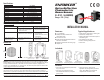
E-931ACC-R1Q
Square Reflector
53 x 63 mm
E-931ACC-BLS1Q
Sensor Mounting
Bracket
Installation and Adjustment:
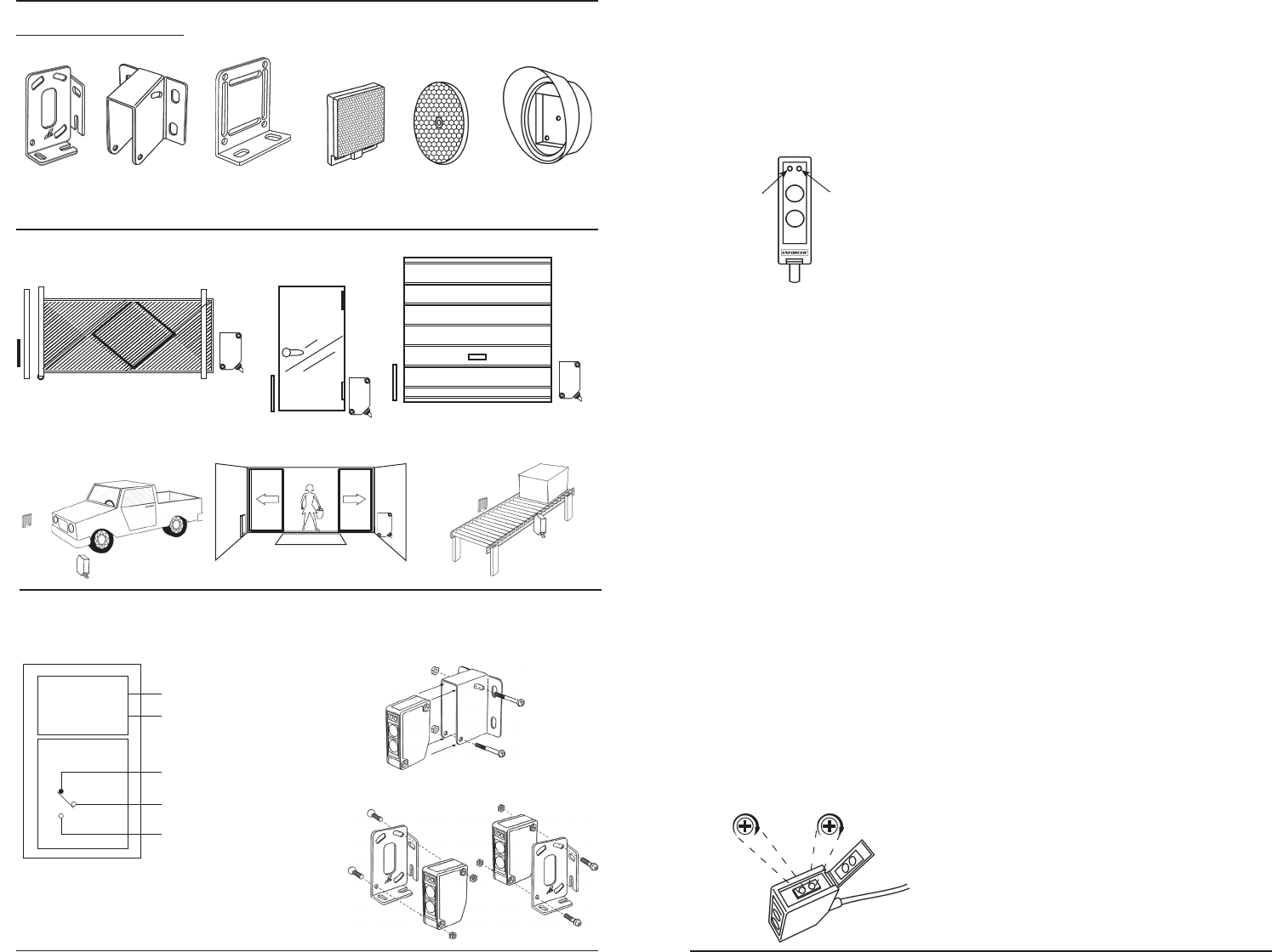
LED Functions:
• Red LED
--
When ON, it indicates the sensor is triggered.
• Yellow LED
--
When ON, it indicates that the sensor is
properly aligned with the reflector, and the sensor is not
triggered.
Sensing Range Adjustment Functions:
The Sensing Range adjustment knob sets how powerful the
infrared signal emitted by the sensor is.
• Min. Setting
--
The infrared power signal emitted by the
sensor is at its minimum or weakest.
• Max. Setting
--
The infrared power signal emitted by the
sensor is at its maximum or strongest.
The objective of this function is to set the appropriate power of
the infrared signal corresponding to the distance between the
sensor and the reflector of a particular application.
The factory default setting is set at "Max.".
Note: If the infrared signal is too strong, the sensor may not
trigger. If the infrared signal is too weak, the sensor
may be susceptible to false alarms.
Response Time Adjustment Functions:
The Response Time adjustment knob sets how long the beam
can be interrupted before triggering.
• Min. Setting
--
The interrupt time is set at 5ms (high
sensitivity) and is suitable for detecting fast moving
objects, but is more susceptible to false alarms.
• Max. Setting
--
The interrupt time is set at 100ms (low
sensitivity) and will reduce false alarms, but fast moving
objects may not trigger the sensor.
The objective of this function is to set the appropriate interrupt
time of the sensor corresponding to the sensitivity required of
a particular application.
The factory default setting is set at "5ms".
E-931ACC-BLR1Q
Square Reflector
Mounting Bracket
Testing:
1. Power up the sensor. The yellow LED should be ON; the red
LED should be OFF.
2. Pass the object to be detected between the sensor and
reflector. The red LED should turn ON and the yellow LED
should turn OFF. This indicates that the object has been
detected.
2
Wiring:
W
e
m
e
c
l
o
Optional Accessories:
E-931ACC-RC1Q
Round Reflector
82 x 9 mm
E-931ACC-HR1Q
Reflector Hood for
Round/Square Reflector
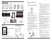
Gate
Gate
Gate
Gate
¤¤¤¤¤¤¤¤¤¤¤
¤¤¤¤¤¤¤¤¤¤¤
Garage
door
¤¤¤¤¤¤¤¤¤¤
¤¤¤¤¤¤¤¤¤¤
¤¤¤¤¤
¤¤¤¤¤
¤¤¤¤¤¤¤¤
¤¤¤¤¤¤¤¤
¤¤¤¤¤¤¤¤
¤¤¤¤¤¤¤¤
Mounting the Sensor:
Sample Installations:
Gate
Main
entrance
door
Store front door
¤¤¤¤¤¤¤¤¤¤¤¤¤¤¤¤
¤¤¤¤¤¤¤¤¤¤¤¤¤¤¤¤
Black (N.O.)
Gray (N.C.)
White (COM)
Relay Output
Multi-voltage
circuit
Brown
Blue
]
12-250VAC or VDC
polarity not important
Connection (5 wires)
Note:
1. Can be connected to AC or DC voltage.
2. Maximum cable extension length is 325 feet (100m).
Vehicle detection Factory assembly line
a. For E-931ACC-BLS5Q bracket
b. For E-931ACC-BLS1Q bracket
E-931ACC-BLS5Q
Sensor Mounting
Bracket
Yellow LED Red LED
Response
Time
Sensing
Range
5ms
100ms
Min Max
Fig. 1
Fig. 2