Installation Instructions For use in GB and IE only C i4 www.contura.
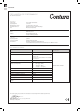
GB 82 CERTIFICATE DECLARATION OF PERFORMANCE No.
GB CONTENTS A warm welcome to Contura. A warm welcome to the Contura family. We hope you will get a great deal of pleasure from your new stove. As a new owner of a Contura stove you have secured a product with timeless design and long service life. Contura also has combustion that is both environmentally friendly and efficient for the best heat production. Read through these installation instructions carefully before installation. Read how to best light your stove in the lighting instructions.
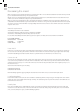
GB 84 FACTS Technical data Output 3-5 kW Nominal output 4 kW Efficiency level Up to 78% Model Weight (kg) Width (mm) Depth (mm) Height (mm) Classic 77 490 420 600 Model Weight (kg) Width (mm) Depth (mm) Height (mm) Modern-3-sided frame 71 490 380 590 Model Weight (kg) Width (mm) Depth (mm) Height (mm) Modern-4-sided frame 72 490 380 635 The connector’s inner diameter is Ø126 mm Type approved in accordance with: European standard EN-13 229 (DE/A) DINplus, Art.
GB Dimensions Dimensions Ci4 Ci4 Classic 300 Flue outlet 45° backwards 420 350 45° 580 530 40 60 550 600 390 40 255 50 300 490 Ci4 Modern 3 - sided frame Flue outlet 45° backwards 415 350 380 300 45° 530 580 40 60 550 590 390 300 40 255 45 490 Ci4 Modern 4 - sided frame 300 45° 530 580 60 45 635 550 40 40 255 45 490 415 350 380 390 300 Flue outlet 45° backwards 85
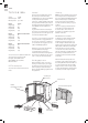
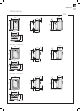
GB 86 RECESSING THE INSERT Recessing the insert When recessing the insert, adjacent walls that are not classed as fire walls or are considered unsuitable for heat loads must be protected by non-combustible material according to the specification below. All joints on the non-combustible material must be sealed using the manufacture’s recommended method. The area between the insert and the recess must be ventilated according to the specification/dimension.
10 GB RECESS EXAmPLE 100 100 50 50 100 100 50 The dimensions are the minimum dimensions, unless otherwise stated. 50 500 ! Wall of combustible material 600 20 Wall of non-combustible material, made of 100 mm aerated concrete in the recess example. 300 800 100 Wall of non-combustible material that is not in contact with combustible material and therefore has no minimum thickness requirement. 800 100 20 max 100 50 500 20 Heat shield 50 100 Area out min.
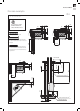
GB INSTALLATION / COMBUSTION AIR Installation in Builders opening Hearth dimensions The appliance must stand on a constructional hearth which meet the building regulations and has minimum dimension as shown in the diagram beside. Always check that the building has enough bearing capacity for the heart, stove and chimney. The stove can be loaded with maximum 100 kg of chimney.
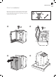
GB PREINSTALLATION Prior to installation Remove loose components as stove base plate and ash tray. Take out the stove body from the convection box by first unscrew the four side bolts and the four bolts for the collar. At last release the convection box from the pallet. ! LEK 10 UM DI NA VA .
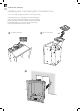
GB 90 INSTALLING AND CONNECTING Installing and connecting the convection box Flue collar 90° straight upwards or 45° backwards If the builders opening is too tight above when the flue collar adapter plate is turned for installation 45° backwards, then remove and fasten the flue collar adapter on the flue. Install the convection box and finally fasten the flue adapter on the convection box, see “Flue collar 45° backwards and tight builders opening” on side 92.
GB INSTALLING AND CONNECTING 3 4 13 No.
GB 92 INSTALLING AND CONNECTING Flue collar 45° backwards and tight builders opening 1 2 3 4 LE K Ø 5 mm 5 6
GB SmOKE CONTROL AREA Smoke control area In smoke control areas it is mandatory to stop the damper from closing completely. In other areas it´s optional.
GB 94 INSTALLING STOVE BODY Installing stove body into the convection box 1 2 x4 ! 3 ! Classic - fasten the screws properly after the stovebody is fitted to the backpanel Modern - fasten the screws only a few turns, they shall be fasten properly first when the cast iron frame are assembled and fitted, see side 95 x4 LEK 10 UM DI NA VA No 10 4 x4 CH E M RO .
GB INSTALLING STOVE BODY Modern frame 1 2 3 4 13 13 o. N 7 7 O o.
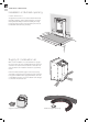
GB 96 INSTALLING FIRE PANELS Installing fire box insulation panels The Thermotte insulation panels are fragile, handle them with care and be careful when placing them into the stovebody.
GB INSTALLING FIRE PANELS 3 4 ! 5 Final inspection of the installation It is very important that the installation is inspected by an authorised chimney sweep before the stove is used. Also read the ”Operating instructions”, before lighting for the first time.
NIBE AB · Box 134 · 285 23 Markaryd · Sweden www.contura.eu 811163 IAV Ci4 SE_EX-5 2014-02-10 Contura reserves the right to change dimensions and procedures described in these instructions at any time without special notice. The current edition can be downloaded from www.contura.