
User Manual

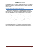
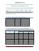
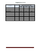
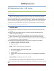
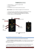
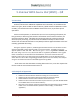
Table Of Contents

Copyright 2012 Page 47
LED2: Yellow
Assistant Scale
Power
Connector
LED1:
Operator
Scale
LED:
Red/Green
1. While pressing “ – “ , connect the power cable
2. All LEDs are highlighted.
3. Release “ – “
4. The module starts normally with LEDs off on the unit.
SPECIAL MODE: Adjust The Maximum Brightness Of The Yellow LEDs
1. During normal use, press ZONE until the green LED brightness increases.
2. By keeping ZONE pressed, the Green LED becomes very bright.
3. Press “ + “ or “ – “ to adjust the maximum brightness of the LEDs
4. Release ZONE to exit the SPECIAL MODE
Figure 5: 5I Lighting Control Unit
8.1.2 5I Manual Scale Illumination Instructions
At Power up, the LED’s will be OFF and consume minimum power.
To alter the brightness of both sets of LEDs, move the Aperture ring to the aperture
setting T22 end-stop and move it away towards T1.4, then repeat that process twice
more within 0.5 second.
This will cause the LED’s to be set to fully ON for 0.3 sec, then fully OFF for 0.3 sec
and then fully ON. The operator can now adjust the desired level by moving the
Aperture scale up (towards T22) or down (towards T 1.4). If there is a half second period
RS232 Serial Cable