
Instructions / Assembly


Ventamatic, Ltd. | 100 Washington Ave, Mineral Wells, TX 76068 ▪ Phone: (800) 433-1626 ▪ www.bvc.com
5
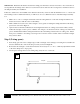
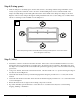
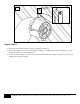
Step 4 (Living space):
Slide the damper box assembly up into the hole and secure it to the ceiling structure using a minimum of a two
inch (2”) long wood or sheetrock screws. Be sure to avoid installing these screws toward the middle of the
damper assembly flanges as the intake grille will screw in at the middle of the damper box flanges as shown in
Figure C. These screws will pass through the ceiling material and into the wooden ceiling joists or lumber in the
attic above ensuring a secure installation of the damper box.
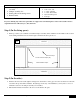
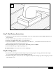
Step 5 (Attic):
Determine to which roof rafter the fan will be mounted. The location of the fan installation will need to be less
than 10 feet away from the damper box assembly due to the length of the provided duct. The further away from
the damper box assembly the fan can be installed the quieter the apparent operation of the fan will be in the living
space below.
Using a 3/8” drill bit, drill a hole in the location chosen. This hole needs to be 1-½” up from the long, flat edge of
the rafter as shown in Figure D.
Attach the rafter bracket to the top of the fan hanging bracket using the provided 5/16” x ¾” bolt, lock nut and
washers.
Attach the rafter bracket to the rafter where the hole was drilled using the provided 5/16” x 2-½” bolt and lock nut
as shown in Figure D.
Ensure all nuts and bolts are tight on the mounting components of the fan.
If possible, manually spin the fan blade to ensure there are no obstructions that may have occurred during
shipping, handling or installation.
C
Note: Avoid placing screws in the middle when mounting the damper box. This area is used to
secure the grille in a later step.