
Instructions / Assembly

Ventamatic, Ltd. | 100 Washington Ave, Mineral Wells, TX 76068 ▪ Phone: (800) 433-1626 ▪ www.bvc.com
7
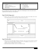
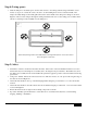
Step 7 (Living space):
NOTE: All electrical wiring supplied and installations must meet or exceed the requirements of local electrical and
fire codes. Wire to 120 Volt, 60 Hz circuit only, using a minimum of 14/2, two-conductor wiring with ground for
the primary wiring run. A minimum of 14/3, three-conductor with ground may be used to wire in between the
switches and the fan unit.
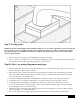
• Disconnect the power supply or switch OFF the appropriate circuit breaker.
• Choose a location on a wall that is close to the fan for installing the switches. Cut the appropriate hole in the wall
to install the UL listed double gang wiring junction box (not provided).
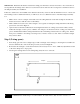
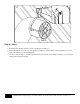
Step 8 (Attic): see wiring diagram on next page
• Open the wiring box on the side of the fan by removing the two screws on the face plate. Keep these screws to re-
close the wiring box after wiring is completed.
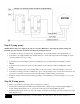
• Run a length of three-conductor wire in between the fan wiring box and the location in the living space below
where the switches will be installed. There should also be the two-conductor wire run from the power supply
panel or breaker box to the switch location.
• Connect the fan High speed (Black) to the Black wire of the three-conductor wire using a wire connector.
• Connect the fan Low speed (Red) to the Red wire of the three-conductor wire using a wire connector.
• Connect the fan Common (White) to the White wire of the three-conductor wire using a wire connector.
• Loosen the Ground screw in the fan wiring box and loop the Ground wire (Bare Copper) around the Ground
screw and tighten down on to the Ground wire.
• Tighten the screws on the cable clamp attached to the side of the fan wiring box to prevent the three-conductor
wire from pulling loose of the fan wiring box.
• Re-close the wiring box by reapplying the face plate and fastening it into place with the original screws.
E