
Instructions / Assembly

8
Ventamatic, Ltd. | 100 Washington Ave, Mineral Wells, TX 76068 ▪ Phone: (800) 433-1626 ▪ www.bvc.com
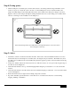
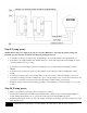
Step 9 (Living space):
NOTE: Ensure that power supply is disconnected or turned OFF before connecting the primary wiring run.
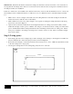
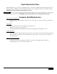
Install the provided switches in a UL listed double gang wiring junction box.
• Connect the incoming power supply wire (usually Black) to the top right terminal of the On/Off switch (1).
• Connect the bottom right terminal of the On/Off switch (2) to the bottom right terminal of the High/Low switch
(3) using a jumper wire (not provided).
• Connect the wire from the High speed motor lead (Black) to the top right terminal of the High/Low switch
(HIGH).
• Connect the wire from the Low speed motor lead (Red) to the bottom left terminal of the High/Low switch
(LOW).
• Connect the incoming common wire (usually White) to the wire from the common lead (White) of the motor.
• Connect the incoming ground wire (usually bare copper) to the grounding screws on each switch (4&5) and to the
ground wire connected to the ground screw in the fan wiring box marked with a ground symbol.
• Install the switches in the UL listed double gang wiring box and install the provided switch plate cover over the
switches.
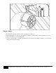
Step 10 (Living space):
• Turn power ON at the power supply panel or breaker box for the fan.
• Test the fan by switching the unit ON using the On/Off switch. Change the speed setting using the High/Low
switch. Ensure that the damper doors open and close when the fan is ON and OFF respectively.
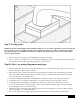
• Install the intake grille to the bottom side of the damper assembly from the living space below using the provided
white-headed screws.