
Installation Guide

6
Ventamatic, Ltd. | 100 Washington Ave, Mineral Wells, TX 76068 ▪ Phone: (800) 433-1626 ▪ www.bvc.com
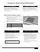
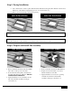
Step 6: Prepare and Install Fan Assembly (cont.)
Push fan assembly through the shutter opening diagonally or through another attic access if doing
a joist-in installation.
Place frame on top of facing or additional frame and draw alignment marks around the base of the
assembly then secure to the facing using screws.
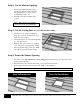
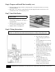
Step 7: Install the Shutter
_*Note* Never operate the fan without the
shutter installed
Draw alignment marks on the ceiling 7/8”
from the edges to indicate the outer edges of
the shutter frame.
Install the shutter using the white-headed
wood screws provided with your fan.
Caulk the seams for an airtight seal.
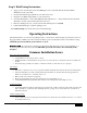
Step 8: Wiring Instructions
*Note* All wiring supplies and installations must meet or exceed the requirements of local electrical
_and fire codes. Wire to 120 Volt, 60 Hz circuit only, using 14-3 two-conductor wiring with ground.
Disconnect the power supply or
switch off the appropriate circuit
breaker.
Open the WiFi hub box by removing
the outside screw.
Connect incoming power supply wire
(Black) to the WiFi hub’s black wire
by pushing the incoming power
supply wire into the connector box.
Connect the incoming common wire
(White) to the common wires from the
unit by pushing the incoming common
wire into the connector box.
Connect the incoming ground wire
(Copper) to the grounding lug in the
WiFi hub box.
Close the WiFi hub box by
reinstalling the outside screw.
Manually rotate fan blade to ensure
there are no obstructions before
turning on the power to the fan.