9000 Series Sensor Installation Guide Your Guide to Permanent 9000 Series Sensor Installation Rockwell Automation Entek P/N 48204
Copyright Notice Copyright © 2003 by Entek IRD International Corporation All Rights Reserved Second Edition 2003 Printed in the U.S.A. This Manual is supplied to the User under license, subject to recall by Entek IRD International Corporation at any time, and the Manual at all times remains the property of Entek IRD International Corporation. The information contained in this Manual is considered confidential.
Contents Table of Contents Introduction . . . . . . . . . . . . . . . . . . . . . . . . . . . . . . . . . . . . . . . . . . . . . . . . . . . . . . . . . 1 9000 Series Sensors . . . . . . . . . . . . . . . . . . . . . . . . . . . . . . . . . . . . . . . . . . . . . . . . . . . 1 Sensor Mounting . . . . . . . . . . . . . . . . . . . . . . . . . . . . . . . . . . . . . . . . . . . . . . . . . . . . . 5 Types of Sensor Mounting . . . . . . . . . . . . . . . . . . . . . . . . . . . . . . . . . . . . . . . . . .
Table of Contents iv Entek 9000 Series Sensor Installation Guide
Terms and Conditions ENTEK IRD INTERNATIONAL CORPORATION GENERAL TERMS AND CONDITIONS 1. CONTRACT. When Customer accepts a Quotation from Entek IRD International Corporation or an affiliate (the entity issuing the quotation being “Entek IRD”) by issuance of a purchase order or otherwise and Entek IRD accepts the order, Customer is deemed to have agreed to all the Terms and Conditions contained herein.
Terms and Conditions 6. CUSTOMER RESPONSIBILITIES. Customer shall be solely responsible for the accuracy and adequacy of the information provided to Entek IRD, and Entek IRD shall not be liable for any damages resulting from the loss, disclosure or inaccuracy of such information.
Terms and Conditions 9. EXCLUSIVE REMEDIES AND LIABILITY LIMITATION. THE REMEDIES PROVIDED HEREIN ARE CUSTOMER'S SOLE AND EXCLUSIVE REMEDIES, AND ENTEK IRD'S EXCLUSIVE LIABILITY WHETHER ARISING IN CONTRACT, TORT (INCLUDING NEGLIGENCE), STRICT LIABILITY OR ANY OTHER LEGAL THEORY.
Terms and Conditions viii Entek 9000 Series Sensor Installation Guide
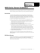
000 Series 1. 9000 Series Sensor Installation This manual shows you how to install the 9000 series sensors. It is intended for anyone who installs or maintains a predictive maintenance system with permanently mounted sensors. Introduction A sensor (also called a transducer) is a device that measures a physical quantity and converts it into a proportional electrical signal, typically voltage or current. This signal is sent through a cable to a central monitoring station.
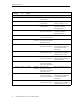
9000 Series Sensors Model Number Part No Bias Output Sensitivity Description Notes General Purpose 9000A 43781I 8–12 VDC 100 mV/g General purpose accelerometer Top exit, Mil Spec connector. 6–8 VDC 100 mV/g General purpose accelerometer Top exit, Mil Spec connector. Low bias voltage (6–8 V). 9000B 43782I 8–12 VDC 100 mV/g General purpose accelerometer Top exit, integral cable 10', 2-conductor shielded, polyurethane jacket.
9000 Series Sensors Model Number Part No Bias Output Sensitivity Description Notes 9200FM 43789I 8–12 VDC 100 mV/g General purpose, precision low profile ring style accelerometer Side exit, Mil Spec connector. Intrinsic Safety Certification by Factory Mutual. 9300 43792I 8–12 VDC 100 mV/g Low cost accelerometer Top exit, Mil Spec connector. 9400 47090I 8–12 VDC 100 mV/g General purpose, low profile side exit accelerometer Side exit, Mil Spec connector.
9000 Series Sensors Model Number Part No Bias Output Sensitivity Description Notes High Temperature 9100T 43805I 8–14 VDC 9150HT 43807I 12–15 VDC 9150HTA 46496 12–15 VDC 9200T 43806I 11–14 VDC 100 mV/g High temperature accelerometer Top exit, Mil Spec connector, -54 to 163 deg C operating range. 100 mV/g High temperature charge Top exit, 2-Pin Mil Spec mode accelerometer connector, -54 to 260 deg C system operating range.
Sensor Mounting Sensor Mounting Next to choosing the correct sensor, the sensor mounting is the most important consideration in getting accurate readings from the sensor. Types of Sensor Mounting The actual frequency range of a sensor depends on how well it is attached to the machine. Mounting sensors directly on the case Mounting sensors directly to the machine is the most common mounting technique for many vibration sensors.
Sensor Mounting Follow the specific sensor’s guidelines for the dimensions of the hole, the type of set screw, and the torque for attaching the sensor. The table below lists the data for the 9000 sensors.
Sensor Mounting When connecting cables for sensors with ground-isolated cases, make sure that the cable shield is not grounded at the sensor end. There are two possible cable configurations: ! In coaxial cable, the center conductor carries the signal and power, while the outer braid provides shielding and signal return. Grounding the shield at the monitoring device and not at the sensor isolates the sensor and prevents ground loops.
Sensor Mounting Mounting sensors with a bracket Sometimes a sensor will not fit at the desired location on or near the bearing housing because of an obstruction or because a suitable flat surface is not available. In these cases, it may be necessary to use a bracket extending from the desired measurement point to an area where the sensor can be mounted properly. Make sure that the bracket itself does not introduce any extraneous vibrations. The bracket must not bend or flex.
Sensor Cable Guidelines Sensor Cable Guidelines This section describes some common cable guidelines to get the signal from the sensor to the monitoring device. Sensor Connections and Power Most of the 9000 series sensors are two-wire, IEPE accelerometers. There are also 9000 series sensors that have a built-in integrator to produce a velocity signal, as well as combination accelerometer/temperature sensors. The pin connections on the sensors are listed in the following table.
Sensor Cable Guidelines Cable Installation The cable from the sensor is a critical component in getting the signal to the monitoring device. The 2-wire cables with shield listed below are dedicated, one per sensor, to carry sensor signals to the monitoring device. Cable run at 10 kHz Cable diam. Belden No. Max. Alpha Temp. No. Up to 500 ft (152 m) 6 dB (2:1) 1 0.168 in 4.27 mm 8641 140° F 60° C 2400C Up to 500 ft (152 m) 12 dB (4:1) 1 0.175 in 4.45 mm 8761 140° F 60° C 2401C 3 0.310 in 7.
Sensor Cable Guidelines Cable length The nomograph below provides a simple, graphical method for obtaining the expected maximum frequency capability of an IEPE measurement system. The maximum peak signal voltage amplitude, cable capacitance, and supplied constant current must be known or presumed.
Sensor Cable Guidelines For example, when running a 100ft. cable with a capacitance of 30 pF/ft, the total capacitance is 3000 pF. This value can be found along the diagonal cable capacitance lines. Assuming the sensor operates at a maximum output range of 5 volts and the constance current signal conditioner is set at 2 mA, the ratio on the vertical axis can be calculated to equal 5. The intersection of the total cable capacitance and this ratio result in a maximum frequency of approximately 10.2 kHz.
Sensor Cable Guidelines For a sensor with a top exit cable connection, make sure there is at least 6 inches of clearance above the machine surface to allow for movement of the sensor and cable. Clamp the cable within 6 inches of the sensor, allowing enough room for the cable to bend without damage. Clamp the cable at intervals to prevent movement. Service loop Cable clamp Machine surface For sensors with a side exit cable connection, clamp the cable 3–4 inches from the sensor.
Sensor Cable Guidelines Splicing cables Splices in cables are acceptable if the connections are soldered. Splices must be located in a junction or conduit box for access. Coil any excess cable in the junction or conduit box, making sure that any exposed (bare) cable shield is taped off so it cannot touch the junction or conduit box. If necessary, you can shorten the armored cable from an accelerometer or velocity sensor by carefully cutting away the armor.
Connecting 9000 Series Sensors to Monitors Connecting 9000 Series Sensors to Monitors This following drawings show the connections between 9000 series sensors and the following types of monitors: 5800 monitors, 6600 monitors, XM modules, and Enwatch units. These show the most common connections. Refer to the manual for your particular monitor for the wiring specific to your monitor.
16 Entek 9000 Series Sensor Installation Guide Common Shield Shield Channel B Signal This shows a dual-channel card. For single-channel card, only wire in top channel Cable shield not connected at this end Pin A - Signal Pin B - Common Common Channel A Signal Note: If shield is connected at the transducer, do not ground the shield at the 5800 monitor end. If shield connection is unknown at the two pin connector, ohm out and verify before wiring.
26 27 28 29 30 31 32 33 34 35 36 37 38 39 40 41 42 43 44 45 46 47 48 1 2 3 4 5 6 7 8 9 10 11 12 13 14 15 16 17 18 19 20 21 22 23 24 Shield Cable shield not connected at this end Cable shield not connected at this end Note: If shield is connected at the transducer, do not ground the shield at the 6600 monitor end. If shield connection is unknown at the two pin connector, ohm out and verify before wiring.
Connecting 9000 Series Sensors to Monitors C O N N E C T IN G 9 0 0 0 S E R IE S IE P E A C C E L E R O M E T E R T O A N E N W A T C H U N IT RX TX J8 LK J11 OB J9 RS-232 DB-9 (female) Status LED's _ + DC Power In Network Input RJ-45 Jack J6 JP 20 3 1 U28 J5 3 JP 19 U20 1 J4 3 JP 18 Mode Select 1 J3 3 2 JP 17 1 RV2 RV3 RV1 A-B A-B A-B A-B A-B A-B A-B A-B A-B A-B A-B A-B A-B A-B A-B J u m p e r i n x A p o s it io n f o r IE P E A c c e le r o m e te r 1-2-3-4-5-6
Connecting 9000 Series Sensors to Monitors CONNECTING 9000 SERIES SENSORS TO XM-120/121/122 VIBRATION MODULE CHANNEL 1 Pin A - Signal Pin B - Common Cable shield not connected at this end Signal Common Channel 1 Input Signal Shield Ground 16 0 37 21 22 5 6 Jumping terminals 5 to 6 & 21 to 22 configure the transducer power supply for IEPE tranducer(s) Note: You may ground the cable shield at either end of the cable. Do not ground the shield at both ends.
Connecting 9000 Series Sensors to Monitors TYPICAL WIRING FOR IEPE ACCELEROMETER TO XM-120/121/122 VIBRATION MODULE CHANNEL 2 Pin A - Signal Pin B - Common Cable shield not connected at this end Channel 1 Input Signal Signal Common Channel 2 Input Signal Shield Ground 17 38 21 22 1 5 6 Jumping terminals 5 to 6 & 21 to 22 configure the transducer power supply for IEPE tranducer(s) Note: You may ground the cable shield at either end of the cable. Do not ground the shield at both ends.
Index Index H 5800 monitors 15 6600 monitors 15 high frequency sensors 3 high temperature sensors 4 A I adhesive mounting 7 attenuation, signal in cable 10 insulated mounting 6 interference, reducing 12 B J Belden number, cable 10 bracket mounting sensors 8 junction boxes 14 C cable coaxial 7 conduit 14 conduit boxes 14 construction 13 guidelines 9 installation 10 length 10, 11 reducing electrical interference 12 splicing 14 coaxial cable 7 conduit 14 conduit boxes 14 connecting 5800 monitors 15 6
Index S sensors connections 9 general purpose 2 high frequency 3 high temperature 4 low frequency 3 mounting 5 mounting on an insulated housing 6 mounting with a bracket 8 mounting with a stud 5 mounting with adhesive 7 overview 1 triaxial 3 velocity output 4 set screws 6 splicing cable 14 T torque, sensor mounting 6 transducers See sensors triaxial sensors 3 V velocity output sensors 4 X XM modules 15 4 Entek 9000 Series Sensor Installation Guide