Portable Air-conditioner Use and Care Manual Thank you very much for selecting this new model of Portable Air Conditioner, please read this Use and Care Manual carefully before installing and using this appliance. Please keep this Use and Care Manual properly for future reference.
Safety Instructions 1. Electrical Specifications 1. All wiring must comply with local and national electrical codes and be installed by a qualified electrician. If you have any questions regarding to the following instructions, please contact a qualified electrician. 2. The unit must be installed in accordance with national wiring regulations. Check available power supply and resolve any wiring problems before installation and operation of this unit. 3.
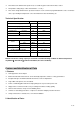
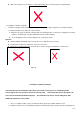
instruction concerning use of the appliance in a safe way and understand the hazards involved. Children shall not play with the appliance. Cleaning and user maintenance shall not be made by children without supervision 3.Cautions: ※ Keep the unit at least 1 meter away from TV or radios to avoid electromagnetic interference. ※ Do not expose the unit under direct sun light to avoid surface color fading. ※ Do not tilt the unit for more than 35 degrees or upside-down while transporting.
※ This unit has two different fan-speed levels, accessible by panel control and remote control. ※ Temperature setting range of this unit is 62-86℉(17-30℃) ※ This unit is designed with various protection functions such as 24-hour programmable timer, auto condensate circle, super intelligent temperature sensor and water-full control and warning etc. Technical Specification: Model Unit NPA-10C Power Supply V~,Hz,Ph 110~120,60,1 Cooling Capacity kW 2.93 Refrigerant/Charge Oz R410A/17.
Screws for window kit assembly. 3 total. 1. Control panel 14. Wire winding pillar 2. Vertical louvers 15. Back shell 3. Horizontal louvers 16. Power cord 4. Air outlet frame 17. Drain hole and cover 5. Front shell 18. Filter 6. Universal wheel 19. Filters 7. Back shell 20. Filter 8. Main vertical louver 21. Chassis 9. Horizontal louvers connecting rod 22. Remote controller 10. Vertical louvers connecting rod 23. Exhaust hose assembly 11.
1. Installation Warning: Keep this mobile air-conditioner in an upright position for at least 4 hours before first installation. Keep the unit in upright position at all times, even when moving to a new location. The air-conditioner should be placed on a flat surface. Do not install or operate this air-conditioner in a bathroom or other wet environments. 1.1 Installation of exhaust hose assembly and its adapter 1) Take out the exhaust hose assembly and its adapter from plastic bag.
Make sure exhaust hose assembly is securely attached by clips in exhaust outlet to avoid it falling off. 1.3 Installation of window seal-plate 1. Install the rectangle end of exhaust hose adapter into the corresponding rectangle hole in window seal-plate assembly, fix it with screw. (Figure B. in Photo below). A. Align the 4 openings on window seal-plate with corresponding 4 tabs on exhaust hose adapter and set them together. B. Slide window seal plate downwards onto the exhaust adapter.
window frame channel that the window slides in. fit the opening. If necessary mark the kit and cut one end down to properly (Figures D, E, and F) 3. Attach screws to window kit adapter, to hold sliding panels in place. This is for vertical installs only. (Figure K) 4. Attach the window kit adapter to the window kit. (Figure G, and I) 5. Place the window kit back into the window with exhaust hose attached to the window kit adapter. (Figure I and J) 6.
2. Move the unit together with its exhaust hose assembly in front of the window and keep the unit at least 50cm away from the walls or other objects. (As Photo). Important notes: The exhaust hose is 280mm-1500mm long. Do not use a different exhaust hose to operate this unit. This unit will only operate properly with the size of the hose provided, and using a different sized hose will affect the performance of the unit.
1. Control Panel This section explains proper mobile air conditioner operation. Figure 3 On/Off button Mode button Up button Timer button Fan speed button Down button Timer indicator Fan speed indicator Water-full indicator Cool mode Fan mode indicator Dehumidify mode indicator Sleep mode indicator Power indicator LED display window Timer indicator Remote control signal receiving window Celsius/ Fahrenheit temperature indicator 2.
Press and buttons together to convert Celsius degrees to Fahrenheit degrees and corresponding indicator will light up. 4) Adjust fan speed Press the 5) button to select a desired fan speed shown below Stand-by Press the button again, the unit will stop working with reminding music sounded, will be red in color. Notice: Working principle for each mode and function 1. Cool mode: When room temperature is 1.8℉(1℃) higher than the set temperature, the compressor and fan will start working.
While the unit is running, Press “Timer” button to set automatic OFF feature, Enter the number of hours you would like the unit to run for. will light up. The unit will turn off automatically when the set time has elapsed. Press “Timer” button to set automatic ON time while unit is off, Enter the number of hours you would like the unit to turn on in. will light up. The unit will turn on automatically and run until it is shut down.
Button: press this button to select “Sleep” function under cooling mode. Before using your remote, install the AAA batteries into remote control. 1. Press and glide the battery cover on the back of the remote control, then you can remove the cover. 2. Insert two new alkaline AAA batteries into the battery compartment. Be sure to note the proper polarity. 3. Reattach the battery cover and make sure the locking tab clicks into place.
The compressor motor will turn off when the compressor is running for over 10 minutes and tube temperature inside the compressor is continuously ≦36℉ for 20 seconds while in cooling mode. An error code of E4 will show on the LED display window, and the unit initiates the anti-frost protection. All buttons on control panel (except for power button) are inactive.
When the water volume reaches its alarm level in the water tank, a warning will sound and the unit will automatically stop working. The water-full indicator “FL” will be flashing on LED display window. A. Put a drainage tray or catch pan below the water outlet at the back of the unit. (Tray is not included) B. Screw off the drain cover, and unplug the water stopper to allow water to flow out of unit into tray. C.
1. Surface cleaning Clean the unit’s surface with a wet soft cloth. Do not use chemical solvents such as alcohol or gasoline to avoid any damage to unit. 2. Filter cleaning Clean the filter every two weeks, otherwise it will affect the performance of the unit, if filter is clogged. 2.1 How to clean filter 1. Grip the filter handle and take it out gently in the correct direction shown by the arrow (as Photo). Notes: Use even force to take out the filter to avoid any twist or damage to filter.
1. Screw off the drain cover, and then pull out the stopper to drain water completely. Note: the tilt angle of the unit must be≦30. 2. Keep the unit running in fan mode for 12 hours, to dry inside of unit completely, to prevent unit from going moldy. 3. Turn off the unit, pull out plug then wrap the power cord around the wire-winding pillar, insert the plug into the universal fixing hole at the back panel of the unit, install the water plug and drain cap. 4.
“E4” once anti-freeze protection is over. Water-full indicator lights The water in chassis is full Drain the water and re-start the unit Appendix Fuse parameters Model: FSD or 50F Voltage: 250V Current: 3.15A Schematic diagram of the air conditioner Capillary Condenser Compressor Evaporator For specific technical parameters of the model, refer to rating label on the product.