Operation and Maintenance Manual 120V/60HZ GLACIER AVALANCHE BLIZZARD CS5-18-VD CS5-18-VD-TB CS6-36-1D CS6-36-VD CS6-50-VD
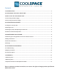
Contents 1.0 INTRODUCTION ............................................................................................................................. 1 2.0 UNPACKING YOUR COOL-SPACE UNIT ...................................................................................... 1 3.0 SET-UP OF THE COOL-SPACE UNIT............................................................................................ 1 3.1 Connecting the water supply ..........................................................................
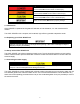
Signal Word Definitions DANGER indicates an imminently hazardous situation which, if not avoided, WILL result in death or serious injury. WARNING indicates a potentially hazardous situation which, if not avoided, COULD result in death or serious injury. CAUTION indicates a potentially hazardous situation which, if not avoided, MAY result in minor or moderate injury. IMPORTANT indicates a potentially hazardous situation which, if not avoided, MAY result in property damage. 1.
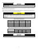
3.2 Connecting the electrical supply The COOL-SPACE unit should be plugged into a fused or circuit breaker protected 15 amp, 120 volt, and 60 Hz circuit. All models utilize standard 120-volt power supply. The unit should be plugged into a fused or circuit breaker protected 15 amp, 120 volt, 60 Hz circuit. Table 1 shows the amperage requirements for the specific models. If an extension cord is required, refer to Table 2 for the proper 3-conductor heavy-duty cord required.
4.0 Operating procedures There are 3 factors to consider when determining where to place the COOL-SPACE unit. 1. Fresh air supply: The inlet side of the unit (pad side) requires a constant, uninterrupted supply of fresh air for maximum performance. A distance of 3 feet clear space to any obstructions at the rear or inlet side of the unit is recommended. 2.
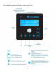
4.4 Intuitive Control Panel Operation The BLIZZARD-50 comes equipped with an intuitive control panel.
5.0 Maintenance and storage ELECTRICAL SHOCK HAZARD Disconnect the power supply before performing any service or maintenance on the unit. Failure to do so may result in serious injury or death. 5.1 Removing the cooling media to access the inside of the unit In order to perform any maintenance on internal components, the cooling pads must be removed to access the inside of the unit. 1. Remove the bolts connecting the pad retainer bar (pad-side) from the housing. 2.
5.4 Storage 1. Remove the pads, as described in section 5.1 2. Clean with a soft brush and water to remove dust and debris (never use bleach) 3. Drain sump using procedure described in section 5.3 and wipe dry 4. Store the COOL-SPACE unit in a dry area. Cover if possible to prevent dust build-up. 6.0 Troubleshooting/Repair 6.1 Troubleshooting ELECTRICAL SHOCK HAZARD Disconnect the power supply before performing any service or maintenance on the unit. Failure to do so may result in serious injury or death.
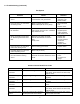
6.1 Troubleshooting (continued) Fan System Problem Check Solution Fan won't run and makes no sound. Power cord, extension cord, switches, circuit breaker, GFI ground fault. Reconnect power or extension cord. Reset breaker. Fan motor won’t run and makes a humming sound. Blade in contact with shroud. Motor stalled (will not turn by hand). Re-center blade hub. Replace motor. Breaker trips or fuse blows when fan is started. Motor stall. Check power source for min. 120volt/15 amp. Extension cord.
6.1 Troubleshooting (continued) Water System The water distribution system consists of two (2) assemblies: o o The Water Inlet Assembly Brass bulkhead fitting Float valve assembly The Hose and Valve Assembly Spray Bar Assembly Valve Assembly Connection Hose Problem Check Solution Floor at side of COOL-SPACE unit is wet Water inlet hose is loose at supply hose or inlet hose is loose at bulkhead fitting. Tighten connections and/or replace hose washers.
6.1 Troubleshooting (continued) Pump Problem Check Solution Pump motor will not run when switch is turned on. Turn fan on to check for power. Is water level high enough to make the low- water cut-off circuit? If fan doesn’t start; check breaker and cord plug-in. If fan does start; check for power to and through pump switch (when turned on). Fill water reservoir. Pump motor hums when switch is turned on, but does not pump water. Obstruction in impellor. Pump motor failure. Remove object(s).
6.2 Repair procedures Repairs should be performed by a qualified technician! ELECTRICAL SHOCK HAZARD Disconnect the power supply before performing any service or maintenance on the unit. Failure to do so may result in serious injury or death. Fan Motor Replacement GLACIER-18 (CS5-16-VD, CS5-16-VD-TB, CS5-18-VD, CS5-18-VD-TB2) 1. Remove cooling pads (see section 5.1 for pad removal instructions) 2. Remove the black motor wiring plate and disconnect motor wires.
6.2 Repair procedures (continued) Pump Replacement GLACIER-18 (CS5-16-VD-TB, CS5-18-VD-TB2) 1. Loosen PVC Union 2. Remove pump and PVC pipe 3. Unplug the cord from the top of the pump by removing 2 screws 4. Unscrew PVC pipe from the pump 5. Reverse steps 1-4 to reinstall the new pump 6. Reinstall cooling pads and guards, reconnect power, and test pump GLACIER-18 (CS5-16-VD, CS5-18-VD) - AVALANCHE-36 (CS6-36-1D, CS6-36-VD) - BLIZZARD-50 (CS650-VD) 1. Unscrew fitting from pump 2.
7.3 Optional Accessories and Replacement Parts Accessories and replacement parts are available from your local distributor or supplier or they can be found online at www.cool-space.com.
315 N Madison Street Fortville, IN 46040 317-577-0417 · 800-557-5716 support@cool-space.com www.COOL-SPACE.