Instruction Manual NVR with Gateway Thank you for your support *Please read the instruction manual carefully before operation. *Please keep the instruction manual for future reference.
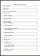
Table of Contents Product Introduction-------------------------------------------------------------------3 Product functions ----------------------------------------------------------------------3 Alarm function-------------------------------------------------------------------------3 NVR Function-------------------------------------------------------------------------4 Restore to Factory Default Settings -----------------------------------------------------4 Technical Parameters---------------------------
6.3 Recording Setting--------------------------------------------------21 7. Alarm event ----------------------------------------------------------21 8. Setting---------------------------------------------------------------22 8.1 Enter the setting interface-------------------------------------------22 8.2 Modify alarm host icon----------------------------------------------22 8.3 Other settings------------------------------------------------------23 9.
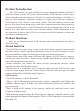
Product Introduction The NVR Gateway is a new intelligent security equipment with the function of NVR and Alarm system. The alarm system includes NVR Gateway, alarm sensor, alarm controller and alarm receiver. The devices send information to each other via specific radio frequency. Different countries or regions have different frequency. NVR Gateway is the "brain" of the whole system.
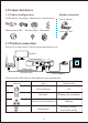
*There is a HDMI interface on the NVR Gateway which can connect with monitor or TV. The maximum resolution of the video display is 1920×1080. With HDMI port, the video from the cameras can be displayed on the HD monitor. * The NVR Gateway has a USB 2.0 interface for mouse and keyboard, which is used for setting menu screen which include storage devices set up and copying files.
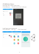
1.Product hardware 1.1 Product configuration Product accessories NVR Gateway Power plug Smoke sensor Contact sensor Power Adapter Motion sensor (PIR) Network Cable Remote control Siren alarm SOS 1.
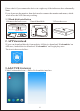
Please check if you connect the devices in a right way if the indicators show abnormally. Note If you do not use the monitor, then don't need to connect the monitor and mouse, which won't affect the NVR Gateway working. 1.3 Hard disk installation 1.Remove the back cover 2.Install hard disk 3.Close the cover Open here 2. APP download *Users can download directly from website. iOS device download “Coolcamkits “on APP store, Android device download “Coolcamkits” on Google play store.
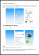
3.1 Product information Click Coolcam kits icon and Coolcam kits interface will appears. Click the icon on the upper left corner, the interface will display the basic information about the product operation manuals and product brochures. 3.2 The step to add NVR Gateway Click Coolcam kits icon, Coolcam kits interface will appears, click add icon on the upper right corner. On NVR Gateway interface, input the basic information about NVR Gateway and click OK. Note 1.
3.When you add NVR Gateway ID, please confirm whether the NVR Gateway UID numbers is the same, otherwise please re-add the UID number. 4.Smart phone app support adding multiple NVR Gateway. 3.3 NVR Gateway Mode Alarm host mode “Arming” and “disarming” Arming: in arming condition, all devices connected to the NVR Gateway can be linked through the NVR Gateway.
4.2 Add Contact Sensor a. Scan QR Code to add the Contact sensor Click Add Sensors Click QR code as below to add sensor b.
b.Input the name of the sensor Click“ ” Note 1. After adding the sensor ID, please confirm whether this ID number is as same as the ID number printed on sensor. If not, please add again. 2. The NVR Gateway can add 10 contact sensors at most. 4.3 Add Power Plug a.
b.Input the name of the sensor Click“ ” Note 1.After adding the sensor ID, please confirm whether this ID number is as same as the ID number printed on sensor. If not, please add again. 2.The method of Add Power plug by scan QR code is the same as Contact sensor, please refer to 4.2. 3.The NVR Gateway can add up to 10 pcs power plug. 4.4 Add PIR Motion Sensor a.
b.Input the sensor name Click“ ” Note 1. After adding the sensor ID, please confirm whether this ID number is as same as the ID number printed on sensor. If not, please add again. 2. The method of Add PIR by scan QR code is the same as Contact sensor, please refer to 4.2. 3.The sensitivity of PIR covers area of PIR detection, only within the detection area, PIR can be triggered, beyond the range of PIR detection, PIR will not be triggered. 4.The gateway can add up to maximum 10 pcs PIR. 4.
b.Input the name of sensor Click “ ” Note 1. After adding the sensor ID, please confirm whether this ID number is as same as the ID number printed on sensor. If not, please add again. 2. The method of Add Smoke sensor by scan QR code is the same as Contact sensor, please refer to 4.2. 3.The gateway can add up to maximum 10 pcs Smoke sensor. 4.6 Adding siren alarm a.
b.Input the name of sensor Click “ ” Note 1. After adding the sensor ID, please confirm whether this ID number is as same as the ID number printed on sensor. If not, please add again. 2. The method of Add Siren Alarm by scan QR code is the same as Contact sensor, please refer to 4.2. 3.The siren alarm can be manually controlled to trigger alarm. 4.The NVR Gateway can add up to 2 siren alarms. 4.7 Add sos a.
b.Input the name of sensor Click “ ” Note 1. After adding the sensor ID, please confirm whether this ID number is as same as the ID number printed on sensor. If not, please add again. 2. The method of Add SOS by scan QR code is the same as Contact sensor, please refer to 4.2. 3.The gateway can add up to 10 pcs SOS. 4.
Pay attention 1.When setting linkage siren alarm, you would set siren alarm linkage turn off/on. when the linkage switch turn on, once the triggered device that connecting with alarm host is triggered, the siren alarm will be triggered alarm; when the linkage switch turn off, any triggered device that connecting with alarm host is triggered, the siren alarm won't be triggered alarm. 2.Any triggered device can set the linkage setting of power plug. 3.
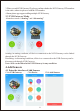
Type in camera basic information---Click confirmed Note: 1.The method of adding camera UID is same as adding gateway, please refer step in 3.2 Camera default password : admin 2.To avoid unauthorized access, please change password when accessing the camera for the first time. 3.The camera can be added to NVR Gateway only when both are under same network. 4.Up to eight cameras can be added to each NVR gateway。 5.
Click to rename Click to revise password Click to delete camera 5.
5.4 Camera Wireless Install Click camera---Click install---Click wifi administration Select wifi, enter password and click confirmed, install finished Note For initial setup of camera, customer should make connection between camera and WiFi router by using one key setup on camera app separately. Once WiFi connection is made between the camera and wifi router, the NVR gateway can search network and add the camera automatically or manually.
6. Recording 6.1 Enter the video interface Click “Alarm host” icon click “Recording” icon enter the video interface 6.
6.3 Recording Setting 1). Enter record setting interface 2). Video setting plan Click “Record setting” icon, and then Slide the “On/Off” key to open video setting plan, enter recording setting interface then click recording date to set the video time. Note * Full-time recording records the video 24 hours a day * Video setting plan means choosing part-time to video * Full-time recording and part-time recording function can not be used at the same time 7.
8. Setting Click “Setting” icon, there are “Alarm host icon setting”, “Password setting”, “Alarm push function setting”, “Alarm recording setting” ,“Push sound setting” ,“Clock setting”, “Format disk setting”, “Restart host setting”” 8.1 Enter the setting interface Click “alarm host” icon---click”event” icon---enter “setting” interface 8.
8.
9. Device information Click “Alarm host” icon--- click “Device information” icon ---view “Device information” 10.NVR Please refer to “1.2 Product Connection Way” from Page 6, To connect all devices including Display Screen and Mouse. Then choose interface channel Of HDMI video signal you access, enter into video monitoring interface. 10.
10.2 Log in User name: admin Password: admin 11.Add devices There is “Automation” and “Manual operation” in IP channel of Menu bar for users to add cameras, P lease check “filter equipment has been added”, Avoid to repeat to add device. 11.1 Manual Add Choose Camera, click add button, enter password to add device.
Click add button, enter password of camera Users can add 8 cameras for final interface 11.2Automatic Add Users can add devices randomly and automatically in LAN, if NVR has connected with other devices, please click automatic add, but please note that IP address of camera might change.
12.System Setup There is “Device information” “Network information” “System information” “Channel information” in system setup column. 12.1 Device Information Users can see device name, device type, software version, disk amount, channel amount, UID number in device information column 12.2 Network Setup Users can set up IP address of device and DNS as well as HTTP port in network column.
13.System Information There is “Basic Settings” “Time Set” “Disk Management” “System Maintenance” in system information column. 13.1 Basic Settings Users can revise the name of Setup, choose Language (Chinese/English), Choose Resolution in Basic setup column. 13.2 Time Set Users can set up time of device and choose time zone.
13.3 Disk Management Users can check status of disk and format the data of disk. 13.4 System Maintenance Restart and Reset button in System Maintenance. 14.Channel Information There is “Display Setup” “Video Parameter” “Audio Parameter” “Recording Plan” “IP Channel Setup” in Channel information column.
14.1Display Setup Users can choose channel in display setup column Display time and display name 14.2 Video Parameter In Video Parameter column, we can choose Resolution(1280X720P/650X352),Data rate, frame rate, video coding control.
14.3 Audio Parameter Volume range from 1-100 14.4 Recording Plan In recording plan column, users can choose video recording file time, choose video recording channel, choose planning video recording data rate, choose time setup for video recording.
Recording Schedule Setup 14.5 IP channel Setup Click search button, choose device, enter password of device to add device, Original password of device is admin.
15. Image Setup Image setup column display Vertical flip, horizontal image, brightness, Saturation, contrast ratio and Chroma.
16. Video Playback On video playback menu, choose date, channel and video type, it will display video file in corresponding channel. User can play, pause, slow playback and fast-forward.
17. Pan/Tilt control On NVR interface, choose device and click right button to choose Pan/Tilt control in menu bar. User can control the direction, zooming and focusing of the camera. 18.
19. 4 images Users can choose channel 1 to 4 as quad image or channel 5 to 8 as quad image. 20. Display Menu bar Click Display Menu bar to display function opetion on the upper left corner of interface.