A90-0132 Modular Multi System Service Manual Air Conditioner – Multi Split Type System HFC R407C
Contents Introduction . . . . . . . . . . . . . . . . . . . . . . . . . . . . . . . . . . . . . . . . . . . . 4 1 Summary . . . . . . . . . . . . . . . . . . . . . . . . . . . . . . . . . . . . . . . . . . . . . . 6 2 Outline of MMS (Modular Multi System) . . . . . . . . . . . . . . . . . . . 8 3 Parts Specifications . . . . . . . . . . . . . . . . . . . . . . . . . . . . . . . . . . . . 10 4 Construction Views – Outdoor Units . . . . . . . . . . . . . . . . . . . . . .
Introduction Precautions 1 Read these Safety Notes carefully before installing this unit. These Safety Notes contain very important safety information. Always be sure to observe these cautions. After installation is complete, trial the operation of the unit to make sure that it is operating normally. Instruct the customer about how to operate the unit, and about necessary maintenance. The dealer or a special contractor must install this unit.
Introduction Components 1. Outdoor Unit 1 Inverter unit Fixed-speed unit Appearance Corresponding HP 8HP Model name 10HP 6HP 8HP 10HP MM-A0224HT MM-A0280HT MM-A0160HX MM-A0224HX MM-A0280HX Cooling capacity (kW) 22.4 28.0 16.0 22.4 28.0 Heating capacity (kW) 25.0 31.5 18.0 25.0 31.5 2.
Summary Operating Conditions 2 The units referred to within this manual conform with the protection requirements of Directives 89/336/EEC Electromagnetic Compatibility and 73/23/EEC Low voltage. Operating conditions of the unit are as follows: Outdoor temperature Room Temperature Room humidity -5 ~ 43°C -15 ~ 21°C 18 ~ 32°C 15 ~ 29°C <80% Cooling Heating Cooling Heating Cooling Note 1: Cooling capacity is rated at the following temperature conditions: Indoor air inlet temperature 27°C DB, 19°C WB.
Summary Operating Conditions 1. Model name OUTDOOR 2 Modular Multi MM–A0280HT A – Outdoor 0280 – 28.0kW (10HP) 0224 – 22.4kW (8HP) 0160 – 16.0kW (6HP) C – Cooling H – Heating T – Inverter X – Fixed Speed INDOOR Modular Multi MM–TU056 B – C (CR) – K (KR) – N – S (SR) – SB – TU – U – Built-In Duct Type Ceiling Type (IR Remote) High Wall Type (IR Remote) Carcase Type Low Wall Type (IR Remote) Built-In Slim Duct Type 2 Way Cassette Type 4 Way Cassette Type 028 042 056 080 112 140 – – – – – – 2.
Outline of MMS (Modular Multi System) Outline of MMS (Modular Multi System) The design of the Toshiba MMS outdoor unit allows for easy unit maneuvering into any standard lift. Its size also allows it to be easily installed in limited spaces. Branching Combination of line and header branching is highly flexible. This allows for the shortest design route possible, thereby saving on installation time and cost.
Parts Specifications Indoor Units Type 4 Way Cassette Type ‘U’ 4 2 Way Cassette Type ‘TU’ Built-In Slim Duct Type ‘SB’ Built-In Duct, Type ‘B’ Ceiling Type ‘C’ High Wall Type ‘K’ Carcase Type ‘N’ Low Wall Type ‘S’ Appearance Model name Capacity code Cooling Capacity Heating Capacity (kW) (kW) MM-U056 MM-U080 MM-U112 2 3 4 5.6 8.0 11.2 6.4 9.6 12.8 MM-U140 5 14.0 15.8 MM-TU028 MM-TU042 MM-TU056 1 1.5 2 2.8 4.2 5.6 3.2 4.8 6.4 MM-SB028 1 2.8 3.
Parts Specifications Outdoor Units COMPRESSOR Model Name Motor Type Power Supply Output (kW) Pole (P) Coil Resistance (Ω) Comp. Oil Name Amount of Oil (ml) Inner Over-load Relay 4-WAY VALVE Model Name Coil Specification MM-A0280HT MM-A0224HT MODEL MM-A0280HX MM-A0224HX MM-A0160HX MG1450CW-21B YG1800CW-B1 YG1700CW-B1 3 – Phase induction motor 380 – 415V, 3 – Phase, 50Hz 7.5 7.5 7.5 7.5 2/2 (INV/Fixed) 2/2 (Fixed/Fixed) 1.18/2.25 (INV/Fixed) 2.25/2.
Parts Specifications Indoor Units Built-In Duct: MM-B140 No. 1 2 3 PARTS NAME TYPE SPECFICATIONS Fan Motor STF-200-140-4F Output (rated) 140W, 4 pole, 200V, 1 Phase 50Hz Running Capacitor – fan motor EAG40M106UF AC 400V 10µF Pulse Motor Valve EDM-B60YPTF-7B-A Capacity: 60 Built-In Duct: MM-B112 No.
Parts Specifications Indoor Units High Wall: MM-K080, MM-KR080 No. 1 2 3 PARTS NAME TYPE SPECFICATIONS Fan Motor MMF-230-27-4R Output (rated) 27W, 4 pole, 230V, 1 Phase 50Hz Running Capacitor – fan motor EEP2W205HQA107 AC 450V 2.0µF Pulse Motor Valve EDM-B40YPTR-7B-A Capacity : 40 High Wall: MM-K056, MM-KR056 No. 1 2 3 PARTS NAME TYPE SPECFICATIONS Fan Motor MMF-230-27-4P Output (rated) 27W, 4 pole, 230V, 1 Phase 50Hz Running Capacitor – fan motor EEP2H155HQA107 AC 500V, 1.
Parts Specifications Indoor Units 2-Way Cassette: MM-TU056 No. PARTS NAME 1 2 3 Fan Motor (x2) Running Capacitor – fan motor (x2) Pulse Motor Valve TYPE SPECFICATIONS PAF-230-7-4 Output (rated) 7W, 4 pole, 230V, 1 Phase 50Hz EEP2H105HQA105 AC 500V, 1.0µF EDM-B40YPTR-7B-A Capacity : 40 2-Way Cassette: MM-TU042 4 No.
Parts Specifications Indoor Units 4-Way Cassette: MM-U140 No. 1 2 3 PARTS NAME TYPE SPECFICATIONS Fan Motor MMF-230-36A Output (rated) 36W, 6 pole, 230V, 1 Phase 50Hz Running Capacitor – fan motor EVM45M305UF AC 450V, 3.0µF Pulse Motor Valve EDM-B60YPTF-7B-A Capacity: 60 4-Way Cassette: MM-U112 No. 1 2 3 PARTS NAME TYPE SPECFICATIONS Fan Motor MMF-230-36A Output (rated) 36W, 6 pole, 230V, 1 Phase 50Hz Running Capacitor – fan motor EEP2W255HQA113 AC 450V 2.
Construction Views Outdoor Units MM-A0280HT, MM-A0280HX, MM-A0224HT, MM-A0224HX, MM-A0160HX Grounding part of bottom plate 755 80 Fixing bolt pitch 630 100 610 100 790 (including fixed leg) 755 Fixing bolt pitch Fixing bolt pitch 5 Base 80 4-15 x 20 (Slot) 700 990 Base 700 Fixing bolt pitch Base bolt position 190 245 88 2-60 x 150 Slot (for transport) 500 (Slot pitch) 235 Refrigerant pipe connecting port (Gas side) braze connection (ØA) 700 1700 1560 90 750 Refrigerant pipe con
Construction Views Indoor Units Built-In Duct MM-B056, MM-B080, MM-B112, MM-B140 Nx Ø200 Air Outlet Unit Dimension:800 Hanging Bolt 4-M10 Provided at site Unit Dimension A Hanging Bolt Pitch B Hanging Bolt Pitch:565 6 x Ø4 holes (Ø160) J=MxK (H) Refrigerant Pipe Connection (Gas ØF) Fresh air inlet Ø125 cut-out (other side) Refrigerant pipe connection (Liquid ØG) Filter kit Drain pipe connection (inner diameter 32) (diameter 32 minimal for PVC pipes) 6 Ensure that there is sufficient space around
158 45 81 333 Shelter board Air flow Optional Air Flow (Lower air inlet) Filter Filter Shelter board 342.5 150 150 Unit dimension Hanging bolt pitch Air outlet 125 700 800 750 700 450 150 342.5 150 Washable filter Air inlet 480 265 276 331 364 391 480 Drain pipe connection (1" BSP threaded connection) Refrigerant pipe connection (Gas Ø12.7) 397 125 Refrigerant pipe connection (Liquid Ø6.4) 200 480 700 150 Hanging bolt pitch 12 35 150 35 Air flow 75 75 37.
Construction Views Indoor Units High Wall MM-K042, MM-K056, MM-K080, MM-KR042, MM-KR056, MM-KR080 158 143 226 A 216 Refrigerant pipe connection (Gas øB) (Both sides) Piping hole 40 (Knockout hole) ø20 (OD.) 372 595 495 900 Drain pipe 40 Air outlet 4-way adjustable Refrigerant pipe connection (Liquid øC) Piping hole (Knockout hole) Model A B 70 118 C MM-K042, MM-KR042 MM-K056, MM-KR056 1149 12.6 1149 12.7 6.4 6.4 MM-K080, MM-KR080 1478 15.9 9.
Construction Views Indoor Units 2-Way Cassette MM-TU028, MM-TU042, MM-TU056 6 20
Construction Views Indoor Units 4-Way Cassette MM-U056, MM-U080 185 73 140 240 Ceiling Knockout for side ducts Ø150 (both sides) 138 195 39 20 Wiring connection Drain pipe connection (Gland plate 3xØ20 holes) (1" BSP threaded connection) 30 40 405 400 268 6 940 195 536 800 Hanging bolt pitch 820 External cassette dimension 880 Ceiling opening 940 Panel dimension 138 30 200 Refrigerant pipe connection (Liquid ØB) 106 259 298 160 106 Refrigerant pipe connection (Gas ØA) 170 100 80
Construction Views Indoor Units 4-Way Cassette MM-U112, MM-U140 185 941 106 106 800 Hanging bolt pitch 820 External cassette dimension 880 Ceiling opening 940 Panel dimension 6 73 140 Drain pipe connection (1" BSP threaded connection) Wiring connection (Gland plate 3xØ20 holes) 940 30 40 610 605 Ceiling 240 138 20 Ceiling panel 138 30 202 348 309 210 Refrigerant pipe connection (Liquid side Ø9.5) 30 39 Refrigerant pipe connection (Gas side Ø19.
1, 2, 3 Fuse (20 AMP) Ferrite Core P Q Temperature sensor FL Accumulator heater Transformer AH TD1, 2 TE TK1, 2, 3 TS Tr Four-way valve Two-way valve Running capacitor 20SF 42, 2 3A, 3B, 3C RC SV High pressure switch 63H 1, 2 Overload relay Electronic flow control valve PMV Inner overload relay 51C 1, 2, 3 1, 2 49C for compressor X Q P GRY X GRY Q GRY P GRY Isolator Y Y RED WHI T2 L1 L2 T1 L2 L3 E N GRY T3 E L3 BLK Power Supply 50Hz 3N~380/415V N N
1, 2 1, 2 1, 2, 3 49C 51C PMV R S T 52C1 U V W 51C1 N L1 L2 L3 P Q MCC-1357-01 10,8 HP (Fixed) 1. The dashed line indicates wiring on the site. 2. and indicates terminal blocks and the numbers within them are terminal numbers. 3. indicates a printed circuit board.
1 1 1, 3 49C 51C PMV R S T 52C1 U V W 51C1 N L1 L2 L3 P Q MCC-1357-01 6 HP (Fixed) 1. The dashed line indicates wiring on the site. 2. and indicates terminal blocks and the numbers within them are terminal numbers. 3. indicates a printed circuit board.
WHI GRY FM GRN/YEL 9 8 7 6 5 4 3 2 1 9 8 7 6 5 4 3 2 1 BRN 9 8 7 6 5 4 3 2 1 9 8 7 6 5 4 3 2 1 BRN Running Capacitor Temperature Sensor Tempterature Sensor Transformer Ferrite Core TC1 TC2 TR FC Q P C B A WHI RED RED Communication Remote Controller (Optional) N L 1. The dashed line indicates wiring on the site. 2. and indicates terminal blocks and the numbers within them are terminal numbers.
Pulse Modulating Valve Name Fuse (PCB) Ferrite Core Fan motor Geared Motor N L Remote Controller (Optional) Communication WHI GRY RED 1. The dashed line indicates wiring on the site. 2. and indicates terminal blocks and the numbers within them are terminal numbers.
Fan Motor Pulse Modulating Valve Pressure Sensor Running Capacitor FM PMV PS RC Tempterature Sensor Transformer Ferrite Core TC2 TR FC Remote Controller (Optional) Communication WHI WHI RED 1. The dashed line indicates wiring on the site. 2. and indicates terminal blocks and the numbers within them are terminal numbers.
Pressure Sensor Running Capacitor PS RC Ferrite Core FC Remote Controller (Optional) Communication WHI RED RED 1. The dashed line indicates wiring on the site. 2. and indicates terminal blocks and the numbers within them are terminal numbers.
WHI WHI Communication Remote Controller (Optional) GRY GRY RC02 RC01 GRY 1. The dashed line indicates wiring on the site. 2. and indicates terminal blocks and the numbers within them are terminal numbers.
Refrigerant Piping Systematic Drawings Inverter Unit (10HP, 8HP) Model: MM-A0280HT, MM-A0224HT Propeller fan M Sensor (TE1) PMV (A) Fan Motor Condenser Condenser Sensor (TS) 4-Way valve Solenoid valve (SV2) Pulse motor valve B (Cooling bypass) (PMVB) 8 Highpressure sensor Sensor (TK1) Check joint (Pd) Strainer Capillary Sensor (TD1) Compressor Strainer Oil tank Check valve Sensor (TK3) Check valve Solenoid valve (SV3A) Compressor case oil removal valve Capillary Solenoid valve (SV42) H
Refrigerant Piping Systematic Drawings Fixed Speed Unit (10HP, 8HP) Model: MM-A0280HX, MM-A0224HX Propeller fan M Sensor (TE1) PMV (A) Fan Motor Condenser Condenser Capillary Sensor (TS) 4-Way valve Solenoid valve (SV2) Pulse motor valve B (Cooling bypass) (PMVB) 8 Sensor (TK1) Highpressure sensor Check joint (Pd) Strainer Capillary Solenoid valve (SV3C) Strainer Check valve Liquid tank Oil separator Check valve Capillary Sensor (TD1) Sensor (TK2) Dryer (x2) Oil tank Check valve Sensor
Refrigerant Piping Systematic Drawings Fixed Speed Unit (6HP) Model: MM-A0160HX Propeller fan Fan Motor M Condenser PMV (A) Condenser Sensor (TE1) Capillary Sensor (TS) 4-Way valve Solenoid valve (SV2) Pulse motor valve B (Cooling bypass) (PMVB) 8 Highpressure sensor Sensor (TK1) Solenoid valve (SV3C) Check joint (Pd) Strainer Liquid tank Strainer Oil separator Capillary Capillary Compressor Strainer Fixed-speed Strainer Check valve Sensor (TK2) Dryer (x2) Oil tank Check valve Senso
Pressure sensor Check joint TC1 Pressure sensor Check joint TC1 Pressure sensor Check joint TC1 TA (Ambient sensor) Evaporator (Indoor unit 3) TA (Ambient sensor) Evaporator PMV TC2 TC2 Packed valve (oil balancing pipe) Packed valve (liquid side) Dryer (x2) Liquid tank PMV (A) Capillary Capillary Service valve (gas side) Check valve (Dotted line) Evaporating gas refrigerant (Low-pressure gas) Check joint (Pd) Compressor Check valve HighHP pressure SW Compressor case oil removal
Pressure sensor Check joint TC1 Pressure sensor Check joint TC1 Pressure sensor Check joint TC1 TA (Ambient sensor) Evaporator (Indoor unit 3) TA (Ambient sensor) Evaporator PMV TC2 Strainer PMV TC2 Strainer PMV Strainer (Indoor unit 2) TA (Ambient sensor) TC2 Packed valve (liquid side) Service valve (gas side) Check valve Capillary Lowpressure sensor Sensor (TD2) Highpressure SW HP Solenoid valve (SV42) Capillary Service valves closed fully at liquid and gas side.
Pressure sensor Check joint TC1 Pressure sensor Check joint TC1 Pressure sensor Check joint TA (Ambient sensor) Evaporator (Indoor unit 3) TA (Ambient sensor) Evaporator PMV Packed valve (oil balancing pipe) Packed valve (liquid side) Dryer (x2) Liquid tank PMV (A) Check valve Service valve (gas side) Check valve (Dotted line) Evaporating gas refrigerant (Low-pressure gas) Check joint (Pd) Compressor Check valve HighHP pressure SW Capillary Check valve Check joint (Ps) Strainer
Pressure sensor Check joint TC1 Pressure sensor Check joint TC1 Pressure sensor Check joint TC1 TA (Ambient sensor) Evaporator (Indoor unit 3) TA (Ambient sensor) Evaporator PMV Packed valve (oil balancing pipe) Packed valve (liquid side) Dryer (x2) Liquid tank PMV (A) Check valve Service valve (gas side) Check valve Check valve Solenoid valve (SV3A) Oil tank Sensor (TK2) Strainer Capillary (Dotted line) Evaporating gas refrigerant (Low-pressure gas) Check joint (Pd) Highpressu
Refrigeration Cycle Schematic Indoor Units Heat exchanger Distributor strainer PMV (D) TC2 TC1 Liquid sensor Gas sensor Capillary tube (B) Check joint Pressure sensor Strainer Strainer Refrigerant Pipe (liquid) (A) Refrigerant Pipe (Gas) (C) Model BUILT-IN DUCT MM-B CEILING MM-C MM-CR HIGH WALL MM-K MM-KR 10 CARCASE LOW WALL BUILT-IN SLIM DUCT 2 WAY CASSETTE 4 WAY CASSETTE MM-N Ø(A) mm Capillary Ø(B) mm Ø(C) mm PMV (D) Code 056 080 112 140 042 056 080 112 140 042 6.4 9.5 9.5 9.
Outline of Control Outdoor Unit Operation start/Operation end The compressor, solenoid valve, pulse motor valve (PMV), outdoor fan, etc. are controlled by a command from the indoor controller. The slave outdoor unit starts/stops by a command from the master outdoor unit.
Outline of Control Outdoor Unit Item 1a. Electronic expansion valve (PMV) control Operation explanation and applied data, etc. (1) PMV A control (PMV x 2) 1) The PMV (pulse motor valve) is controlled between 100 ~ 1000 pulses during the operation. 2) The PMV is fully open during the cooling operation (PMV A1 = 500 pulses, PMV A2 = 500 pulses).
Outline of Control Outdoor Unit Item Operation explanation and applied data, etc. 2b. Outdoor fan control (1) Heating fan control 1) The number of waves is controlled according to the TE sensor temperature. 2) If TE >20°C is constantly detected for 5 minutes, the operation will automatically shut down. This is the same condition as when the thermostat automatically becomes switched off, thus the operation will automatically start again.
Outline of Control Outdoor Unit Item Operation explanation and applied data, etc. 5. Oil equalizing control This control is to prevent oil reduction in the compressor between the outdoor units. This control is classified into two functions, one is an individual control in normal operation which is performed by the master outdoor unit, and the other is a system control which is executed when shortage has been detected in the oil level detection control.
Outline of Control Outdoor Unit Item 7. Release valve control Operation explanation and applied data, etc. Remarks (1) SV2 gas balance control This control is executed to balance the gas by opening SV2 while the compressor is off, in order to decrease the activation load in the next compressorON time. This control is individually executed by the master outdoor unit and each slave outdoor unit. 1) Control conditions When the compressor is switched from ON to OFF operation.
Outline of Control Outdoor Units Item Operation explanation and applied data, etc. 9. Compressor winding heating control This control is to prevent stagnation of refrigerant in the compressor case by a supply of current to heat the windings while the inverter compressor is off. This control is executed by the inverter outdoor unit only. If the supply of current is not turned on for a specified time before trial operation, when installation work has finished, a fault of the compressor may occur.
Outline of Control Outdoor Units Item 11. IPDU (Inverter) control Operation explanation and applied data, etc. Remarks IPDU controls the inverter compressor by command frequency, frequency up/down speed, and current release control value from the interface P.C. board. The main controls of IPDU control P.C. board are described below. (1) Current release control The output frequency is controlled by AC input current value which is detected by T02 on the control P.C.
Outline of Control Outdoor Units Item 12. Defrost control (reverse defrost method) 11 Operation explanation and applied data, etc. Remarks (1) Conditions for starting the defrost operation 1) Calculate the operation time when the TE sensor detects below – 1°C during heat mode. When the compressor is activated, start defrost after 25 minutes for the first time and after 55 minutes for the second time and thereafter.
Outline of Control Outdoor Units Item 12. Defrost control (reverse defrost method) Operation explanation and applied data, etc. Remarks 3) For the slave outdoor units • The compressors 1 and 2 are kept on. Should they be off they will be switched on. • After the signal to finish the defrost operation is received from the master outdoor units, the 4-way valves become switched on. • The capacity of the compressors is controlled according to the on/off signals from the master outdoor units thereon.
Outline of Control Outdoor Units Other cautions (1) Cooling operation in low ambient temperature 1) When low pressure is reduced, the freeze prevention control by the indoor unit TC sensor may decrease the frequency. 2) When low pressure is reduced, the cooling capacity control may decrease the frequency. 3) When discharge temp. sensor value reduces below 60°C, the frequency may be increased over the receive command from the indoor unit. 4) No.
Outline of Control Indoor Units Item Operation explanation and applied data, etc. 1. Power source is reset (1) Automatic remote controller function setup Based upon the result of selecting indoor unit model, setup and display range of the remote controller. 2. Operation select (1) Based upon the operation select command from the remote controller or central controller, the operation mode is selected. 3. Room temp.
Outline of Control Indoor Units Item 6. Air volume control Operation explanation and applied data, etc. (1) By the command from the remote controller or the central controller, “HIGH”, “MED.”, “LOW”, or “AUTO” operation is permissible. (2) While air volume is in AUTO mode, the air volume is changed according to the difference between Ta and Ts. HEAT COOL +2 +1 HIGH +1 Ts LOW Ts MED. -2 7. Freeze prevention control (Low temp.
Outline of Control Indoor Units Item Operation explanation and applied data, etc. Remarks 11. Auto louver control (1) When the louver signal has been received from the remote controller or the central controller, the auto turn louver operates if the indoor fan is operating. 12. Frequency fix operation (Trial operation) (1) When holding the START/STOP SW on the remote controller continuously for 5 seconds, the mode changes to Trial operation mode.
Self Diagnostic Display Information Outdoor Units System information data display (Displayed on the inverter unit only) The combination of rotary switches SW01, SW02 and SW03 display the following info: SW01, 02, 03: Rotary switch SW04, 05: Push switch SW08: Dip switch SW03 SW02 SW01 3 1 1 Displayed content Use refrigerant Type of refrigerant used is displayed. A • In case of R22 model 22 • In case of R407C model 40 2 Outdoor system capacity A B [HP] 3 No.
Self Diagnostic Display Information Outdoor Units Outdoor unit information data display (Displayed on each outdoor unit) SW03 SW02 SW01 1 1 1 Displayed content Check code A [U1] to [U5]: Outdoor unit number (1: Inverter) B [– –]: Normal time (No error), a check code is displayed in abnormality. Push function: Only fan of unit in which an error occurred operates. Push function: Only fan of normal unit operates. Push function: Fan operation function is interrupted.
Self Diagnostic Display Information Outdoor Units (3) Outdoor cycle data display (Displayed on each outdoor unit) SW03 SW02 SW01 2 1 1 Displayed content Pd pressure sensor 2 Ps pressure sensor 3 TD1 temp. sensor 4 TD2 temp. sensor 5 TS temp. sensor 6 Temp. sensor data is displayed with (°C). Symbol • Symbol display and data display are alternately exchanged every several seconds. Symbol • If data is negative data, [– ] is displayed. – 8 TK1 temp.
Self Diagnostic Display Information Outdoor Units (5) Outdoor unit information data display (Displayed on inverter unit only) SW03 SW02 SW01 1 to 3 1 to 16 4 5 6 Displayed content Indoor communication/ Receive status A [01] to [48]: Indoor address number B [ 1]: Receiving, [– –]: No connection Indoor check code A [01] to [48]: Indoor address number B [– –]: No error, a check code is displayed when an error occurs. A A [01] to [48]: Indoor address number B Corresponded HP is displayed.
Control Circuit Configuration Indoor Units (1) LED display on indoor P.C. board – MCC-1361-01 General type Part No. Colour D13 Orange D11 Green D22 Red D51 Yellow Displayed content Details Serial receive Flashes synchronized with the receive signal to the standard remote controller. Serial send Flashes synchronized with the send signal from the standard remote controller. Alarm stop display Goes on when the indoor unit stops with fault.
Control Circuit Configuration Indoor Units (2) Display on remote controller In the following conditions, “STANDBY” is displayed on the remote controller. 1) “STANDBY” display Fan operation is available, but PMV of the indoor unit is not permissible. (Refrigerant does not flow.) a. Indoor unit over capacity When the total HP of the connected indoor units exceeds 1.35 times of outdoor HP, the indoor unit will display “STANDBY” mode.
Control Circuit Configuration Indoor Units (4) Switch positions at shipment from the factory SW No. Function Description SW01 Indoor unit No. Group operation control setup setup1: Master unit 2 to 16 Slave units SW02 Network address setup ON Address setup by remote controller is unavailable. OFF Address setup by remote controller is available. No.7 For contents of address setup, see the next page. SW03 SW06 TA adjust Ceiling height No. 1 ON Normal No. 2 OFF Normal No.
Control Circuit Configuration Indoor Units (5) Contents of switch setup Network address setup table by DIP switch (SW02) • After turning off the power source, set 7 of DIP switch (SW02) to ON. Address setup from the remote controller becomes unavailable. Address No.
Control Circuit Configuration Indoor Units (6) Service P.C. board selection corresponded table MCC-1361-01 The indoor control P.C. board can correspond to multiple models. When replacing MCC-1361-01 P.C. board assembly, set DIP switch, rotary switch, and jumper according to the following description.
Troubleshooting Remote Controller Check Display Main Remote Controller Operating and Reading the Check Display Push the CHECK button, and the identification number of the faulty indoor unit is shown in the Temperature Setup section of the display – and the check code is shown in the TIME section of the display. If the air filter cleaning sign is displayed, the number of indoor units with a filter problem is indicated, followed by the check code.
Troubleshooting Remote Controller Check Display 7-Segment Display Hexadecimal notation Decimal notation Filter Data Example: A Filter signal is sent from No. 1 and No. 15 units under grouping operation. Check Data Unit No. 14 Check code detected at first Check code detected at last Example: Room Temp. sensor of No. 1 is defective. In No. 15, first the Heat Exchanger sensor has failed. Next, the indoor/outdoor inter-unit wire (bus communication line) is defective.
Troubleshooting Self Diagnostic Function Liquid crystal remote controller CHECK code STANDBY display Over capacity Abnormal phase connection Indoor drain overflow alarm Fixed Speed outdoor unit Inverter outdoor unit Remote Controller Remote Controller Remote controller serial signal circuit “99” Indoor Unit Indoor Unit Outdoor Unit Indoor sensor (TA) short or open circuit “0C” Indoor heat exchanger sensor (TC1) short circuit “93” Indoor heat exchanger sensor (TC2) short circuit “94” Indoor pressure s
Troubleshooting Diagnostic Procedure for Check Code Check code Operation cause [04] Inverter communication alarm 1. Connection error of communication cable between inverter and interface P.C. boards 2. Defective interface P.C. board 3. Defective inverter P.C. board 4. Noise from outside 5. High level refrigerant leak if RBC-RD2-PE fitted. Is communication connector between inverter and interface P.C. boards connected? No [ Check connection On inverter P.C. board:CN07 On interface P.C.
Troubleshooting Diagnostic Procedure for Check Code Check code Operation cause [0b] Indoor water overflow alarm Is drain pump connected? 1. Float switch disconnection 2. Drain pump operation error 3. Drain hose blockage Check connection of connector CN11 (Drain pump: Indoor main, P.C. board (MCC-1361-01)) No Yes Does float switch operate? No Is circuit wiring normal?(*1) Yes Check and modify wiring circuit.
Troubleshooting Diagnostic Procedure for Check Code Check code Operation cause [11] Indoor fan motor alarm Does indoor fan operate for a short period after resetting and resuming? 1. 2. 3. 4. Fan motor circuit connection error Capacitor error Fan motor error Defective indoor P.C. board No Yes Is there a connection error of CN18 connector? Yes No Is there a connection error of CN07 connector? Yes Modify connection and wiring. No Is approx.
Troubleshooting Diagnostic Procedure for Check Code Check code Operation cause [14] G-Tr short circuit protective system alarm (Gate Transistor) Is the power source voltage of the outdoor unit normal? 1. 2. 3. 4. 5. Outdoor unit power source error Wiring error on inverter P.C. board AC fuse disconnection Inverter compressor error Defective inverter P.C. board No Confirm the power source supply. Yes Is the connection of the wiring connector on the inverter P.C.
Troubleshooting Diagnostic Procedure for Check Code Check code Operation cause [17] Current detect circuit system alarm Is wiring connector on inverter P.C. board normal? 1. Defective wiring of inverter P.C. board 2. Defective inverter P.C. board No Modify connection of wiring Yes Check inverter P.C. board. Check code Operation cause [18] TE1 sensor open/short TA sensor open/short TE1 sensor open/short has been detected.
Troubleshooting Diagnostic Procedure for Check Code Check code Operation cause [1d] Compressor alarm Is the power source voltage of the outdoor unit normal? 1. 2. 3. 4. 5. Outdoor unit power source error Inverter compressor circuit system error Inverter compressor error Inverter compressor refrigerant stagnation Defective inverter P.C. board No Confirm the power source supply.
Troubleshooting Diagnostic Procedure for Check Code Check code Operation cause [1F] Compressor break down Is the power source voltage of the outdoor unit normal? 1. Outdoor unit power source error 2. Inverter compressor circuit system error 3. Inverter P.C. board error No Confirm the power source supply. Yes Does the voltage reduction occur when the fixed-speed compressor has been activated? Yes No Is the wiring connection on the inverter P.C. board correct? No Modify wiring connector.
Troubleshooting Diagnostic Procedure for Check Code Check code Operation cause 1. 2. 3. 4. 5. 6. 7. 8. 9. 10.
Troubleshooting Diagnostic Procedure for Check Code Check code Operation cause [22] High-pressure protective operation Is the high-pressure sensor characteristics normal? 1. 2. 3. 4. 5. 6. 7. Pd sensor error Service valve closed Outdoor fan, capacitor error Indoor/Outdoor PMV blockage Outdoor heat exchanger blockage SV2 circuit blockage Communication error between indoor and outdoor units No Check parts. If defective, replace. Yes Is service valve fully open? No Open service valve fully.
Troubleshooting Diagnostic Procedure for Check Code Check code Operation cause [87] Missing phase Missing phase of outdoor unit power source A Phase of the outdoor unit power source is missing. Modify the power source wiring. Check code Operation cause 1. No. of connected indoor units/connected over capacity. 2. Incorrect setup of indoor unit HP.
Troubleshooting Diagnostic Procedure for Check Code Check code Operation cause [8d] Reduction in the No. of connected outdoor units Is the system setup of the slave outdoor unit being completed? 1. Outdoor unit system setup 2. Outdoor unit power source 3. Connection error of communication cable between outdoor units 4. Connection error of BUS communication 5. Interface P.C. board error Yes Clear the alarm,and the operation starts (*1).
Troubleshooting Diagnostic Procedure for Check Code Check code Operation cause [8F] Duplicated terminal outdoor addresses Is SW09 bit 1 of master outdoor interface P.C. board off (*1)? 1. Address setup of outdoor unit was duplicated 2. Interface P.C. board error No Turn off SW09 bit 1 on interface P.C. board of master outdoor unit. Yes Reset the power source and execute automatic address. Yes Id [8F ] detected No It is normal. Restart the operation. Yes Check interface P.C. board.
Troubleshooting Diagnostic Procedure for Check Code Check code Operation cause [95] Communication alarm between indoor and outdoor Is there a miswiring or disconnection of PQ communication cable? 1. Connection error of communication cable (PQ) between indoor and outdoor units 2. Connection error of connector for indoor communication, P.C. board error 3. Connection error of connector for outdoor communication, interface P.C. board error Yes Check communication cable.
Troubleshooting Diagnostic Procedure for Check Code Check code Operation cause [96] Consistency detection of indoor and outdoor addresses Is the wiring connection to the communication cable (PQ) normal? 1. Connection error of communication cable (PQ) between indoor and outdoor units 2. Abnormal No. of connected indoor units 3. Wiring connection error of central management remote controller No Modify communication cable.
Troubleshooting Diagnostic Procedure for Check Code Check code Operation cause [97] BUS communication alarm (1) 1. Connection error of communication cable (PQ) between indoor and outdoor units 2. Connection error of (XY) for outdoor units 3. Power source system error of the central controller and indoor unit 4. Noise of peripheral devices 5. Power failure 6. Indoor P.C. board error, central controller error Are X,Y and PQ communication cables normal? No Check communication cable.
Troubleshooting Diagnostic Procedure for Check Code Check code Operation cause [98] BUS communication alarm (2) Is the wiring connection of communication cables to X,Y normal? 1. Miswiring of XY communication cables 2. Duplicated network addresses 3. Indoor P.C. board error, central controller error No Check connection of wiring. Yes Is [98] displayed only on the central controller? No Yes Is connection of CN602 connector on interface P.C.
Troubleshooting Diagnostic Procedure for Check Code Check code Operation cause [99] Indoor remote controller communication alarm Are A, B, C internal wires normal? 1. 2. 3. 4. Remote controller circuit connection error Duplicated indoor No.1 units Remote controller error Indoor P.C. board error No Check connection of wiring. Yes Check indoor P.C. board. If defective, replace. Yes Is there a connection error? No Is group operation performed? Yes No Is SW01 set to No.
Troubleshooting Diagnostic Procedure for Check Code Check code Operation cause [9A] Miswiring/Misconnection of indoor Was the outdoor unit stopped for 20 minutes or more before checking miswiring? No 1. Miswiring/Mispiping of indoor/outdoor units 2. Insufficient refrigerant 3. Blockage in pipe run Stop the outdoor unit for 20 minutes or more, and then check miswiring again. Yes Yes Did you check miswiring according to the temp. conditions Table 1? Is 9A displayed again? No No Wiring is correct.
Troubleshooting Diagnostic Procedure for Check Code Check code [A0] TD1 sensor alarm Operation cause TD1 sensor open/short Open/short of TD1 sensor was detected. Check connector (TD1 sensor: CN502) and characteristics of sensor resistance value. When sensor is normal, replace interface P.C. board of the outdoor unit. Check code [A1] TD2 sensor alarm Operation cause TD2 sensor open/short Open/short of TD2 sensor was detected.
Troubleshooting Diagnostic Procedure for Check Code Check code Operation cause [A6] Discharge temperature TD1 alarm Are the gas pipe and liquid pipe service valves of the outdoor unit fully open? 1. 2. 3. 4. 5. Outdoor unit service valve closed Cooling bypass PMV error TD sensor error Insufficient refrigerant, blockage in pipe Blockage of PMV assembly on the liquid line No Open valves fully. Yes Is there a blockage in the PMV assembly on the liquid line? Yes Replace both the PMVs.
Troubleshooting Diagnostic Procedure for Check Code Check code Operation cause [A7] TS condition gas leak detection Are the gas pipe and liquid pipe service valves of the outdoor unit fully open? 1. 2. 3. 4. Outdoor unit service valve closed Blockage PMV assembly on the liquid line TS sensor error Insufficient refrigerant, blockage in pipe No Open valves fully. Yes Is there a blockage in the PMV assembly on the liquid line? Yes Replace both the PMVs.
Troubleshooting Diagnostic Procedure for Check Code Check code Operation cause [Ab] Pressure sensor misconnection Is the pipe connection position of Pd sensor/Ps sensor correct? 1. Connector misconnection of Pd/Ps sensors 2. Pd/Ps sensor error 3. Compressor inverse operation, compressor error Check connection.
Troubleshooting Diagnostic Procedure for Check Code Check code Operation cause [AE] TD1 condition gas leak detection Are the gas pipe and liquid pipe service valves of the outdoor unit fully open? 1. 2. 3. 4. 5. 6. Outdoor unit service valve closed Cooling bypass PMV error TD1 sensor error Insufficient refrigerant, blockage in pipe Blockage of indoor filter Blockage of PMV assembly on the liquid line No Open valves fully.
Troubleshooting Diagnostic Procedure for Check Code Check code Operation cause 1. Ps sensor error 2. Ps sensor connection error 3. Compressor error [b4] Ps sensor alarm Are Pd sensor/Ps sensor correctly connected? Check connection. Pd sensor: CN501 Ps sensor: CN500 No [ ] Yes Are the output voltage characteristics of Ps sensor normal? No Sensor error Yes Is the low-pressure below 0.95MPa during operation of compressor? No Check compressor. Yes Check interface P.C. board.
Troubleshooting Diagnostic Procedure for Check Code Check code Operation cause [bb] Discharge temperature TD2 alarm Are the gas pipe and liquid pipe service valves of the outdoor unit fully open? 1. 2. 3. 4. 5. Outdoor unit service valve closed Cooling bypass PMV error TD sensor error Insufficient refrigerant, blockage in pipe Blockage of PMV assembly on the liquid line No Open valves fully. Yes Is there a blockage in the PMV assembly on the liquid line? Yes Replace both the PMVs.
Troubleshooting Diagnostic Procedure for Check Code Check code Operation cause [bd] Mg-SW protective operation Is the Mg-SW contact faulty? 1. 2. 3. 4. Mg-SW contact deposit protective operation TD sensor error Pd sensor/Ps sensor error Insufficient refrigerant, blockage in pipe Yes Turn off the power supply, and replace Mg-SW.
Troubleshooting Diagnostic Procedure for Check Code Check code Operation cause [bE] Low-pressure protective operation No Does the indoor fan operate? Yes 1. 2. 3. 4. 5. 6. 7. Ps sensor error Service valve closed Indoor fan capacitor error Indoor/outdoor PMV blockage Indoor heat exchanger blockage SV2 circuit Incorrect wiring of communication cable between indoor and outdoor units Are the following items related to indoor fan motor normal? 1. Connection 2. Capacitor 3. Motor No Repair defective part.
Troubleshooting Diagnostic Procedure for Check Code Check code Operation cause [d1] Master outdoor unit setup alarm Are there multiple inverter outdoor units connected? 1. No. of connected inverter outdoor units 2. Incorrect setup of master outdoor unit 3. Defective outdoor interface P.C. board Yes Set only one inverter outdoor unit per system. No Is setup of the master outdoor units position duplicated? [Set SW08 bit 2 on interface P.C. board of each unit.
Troubleshooting Diagnostic Procedure for Check Code Check code [d2] Slave outdoor unit alarm Operation cause Defective slave outdoor unit An error occurs in the slave outdoor unit. Confirm the check code of the slave unit, and check it according to the diagnostic procedure for each check code. Check code [d3] TH sensor alarm Operation cause Error of temp. sensor incorporated in IGBT (Inverter Gate Bi-Polar Transistor) There is an error with the temp. sensor incorporated in IGBT.
Troubleshooting Diagnostic Procedure for Check Code Check code Operation cause [d7] Protection of low oil level detection Are balancing pipe valves of all outdoor units fully open? 1. Balancing pipe valve (all outdoor units in the connecting line) closed 2. Compressor case oil removal valve closed 3. Miswiring of TK1 sensor/TK2 sensor 4. Refrigerant stagnation in compressor case 5. SV3A, SV3B, SV3C valves error 6. Blockage in oil return circuit of oil separator 7.
Troubleshooting Diagnostic Procedure for Check Code ( *1) 2-way valve leakage/blockage check procedure 1. After resetting the power supply, start a trial operation. 7 segment display 2. Set SW01/SW02/SW03 on interface P.C. board to When operation has started "OL" "– –" During detection of oil level "OL" "FF" or "Numeral" 1/16/1, respectively. 3. Check the 7 segment display of the interface P.C. board. Judgement result of oil level "OL" "AO" or "A1" In case of judgment result “A0” Oil level is adequate.
Troubleshooting Diagnostic Procedure for Check Code Check code Operation cause [d9] TK2 temperature detection circuit alarm Is TK2 sensor out of place? 1. TK2 sensor out of place, miswiring, resistance value characteristics error 2. Oil tank peripheral circuit error Check valve leakage Capillary blockage Strainer blockage [ ] Yes Modify sensor mounting. No Is TK2 sensor in contact with discharge pipe? Correct the pipe so that the TK2 sensor circuit does not touch the discharge pipe.
Troubleshooting Diagnostic Procedure for Check Code ( *1) Oil tank peripheral circuit leakage/blockage check procedure 1. After resetting the power supply, start a trial operation. 2. Set SW01/SW02/SW03 on interface P.C. board to 1/16/1, respectively. 3. Check the 7 segment display of the interface P.C. board.
Troubleshooting Diagnostic Procedure for Check Code Check code Operation cause [dA] Abnormal overheat of heat sink Is power supply voltage normal? 1. 2. 3. 4. 5. Power supply failure Outdoor fan error Heat sink installation failure Blockage of heat sink cooling duct Defective inverter P.C. board No Check power supply. Yes Is the wiring connector connection normal on the inverter P.C. board? Check the circuit wiring, for example wiring to the inverter compressor or connector connection.
Troubleshooting Diagnostic Procedure for Check Code Check code Operation cause [db] Oil level detection circuit blockage detection Is there miswiring of TK1/TK2/TK3 sensor? 1. Blockage in SV3C valve 2. Blockage in SV3C valve circuit [ Yes No Is the resistance value characteristics of TK1/TK2 sensor normal? Modify miswiring. TK1 sensor: CN516 TK2 sensor: CN515 TK3 sensor: CN507 No ] Sensor error.
Troubleshooting Diagnostic Procedure for Check Code Check code Operation cause [dC] Oil level detection circuit leakage detection Is the resistance value characteristics of TK1 sensor normal? 1. SV3C valve leakage 2. TK1 sensor resistance value characteristics error 3. Outdoor unit operation in high external temperatures No Sensor error. Yes Is it an operation in high ambient temperature? (Outside temp.
Troubleshooting Diagnostic Procedure for Check Code Check code Operation cause [dd] Outdoor refrigerant leakage detection Is there a blockage in the PMV assembly on the liquid line? 1. 2. 3. 4. 5. Leakage of PMV assembly on the liquid line Pd sensor/Ps sensor error Blockage in SV2 valve circuit Blockage in SV3B valve circuit Blockage in capillary of bypass between gas pipe and heat exchanger line Yes Replace both the PMVs.
Troubleshooting Diagnostic Procedure for Check Code Check code [dE] Indoor address undefined Operation cause 1. 2. 3. 4. Indoor unit in automatic addressing mode Indoor unit P.C. board setup error Defective indoor unit P.C. board Communication noise interference While this check code is displayed, wait for a moment. When the address is defined, the operation is automatically reset. However, if the check code does not disappear 20 minutes after the power source was turned on, a fault is considered.
Troubleshooting Diagnostic Procedure for Check Code Check code Operation cause 1. 2. 3. 4. 5. 6. 7. 8. Fixed-speed compressor high-pressure SW error Fixed-speed compressor IOL operation Service valve closed Outdoor fan, capacitor error Indoor/Outdoor PMV blockage Outdoor heat exchanger blockage SV2 circuit blockage Miswiring of communication between indoor and outdoor units 9. Pd sensor error 10.
Troubleshooting Diagnostic Procedure for Check Code Check code Operation cause [E5] Inverter IOL operation Is the IOL circuit normal? 1.Connector 2.Wiring 3.Outdoor P.C. board 1. 2. 3. 4. Inverter IOL operation Service valve closed Cooling bypass PMV error Miswiring of communication between indoor and outdoor units No Repair IOL circuit. Yes Are the gas pipe and liquid pipe service valves of the outdoor unit fully open? No Open valves fully.
Troubleshooting Diagnostic Procedure for Check Code Check code Operation cause [E6] Fixed-speed IOL, OL system alarm (1) [F1] Fixed-speed IOL, OL system alarm (2) 1. 2. 3. 4. 5. Power supply error Fixed-speed compressor IOL operation Service valve closed Blockage in indoor/outdoor PMV Miswiring of communication between indoor and outdoor units [E6]: IOL operation circuit error compressor 1 side [F1]: IOL operation circuit error compressor 2 side Does OCR operate? Check the OCR reset button.
Troubleshooting Diagnostic Procedure for Check Code Segment Display Function Outdoor unit 7 segment display (Interface P.C. board) A 7 segment LED to check the operation status is provided on the interface control P.C. board. The display contents can be selected by combining the setup numbers of the rotary switches (SW01, SW02, and SW03) on the P.C. board.
Troubleshooting Description of Functional Parts Functional part Solenoid valve Functional outline 1. SV3A (CN312) 1) Accumulates oil from the compressor to the oil tank when the valve is shut. 2) Supplies the gathered oil to the balancing pipe during ON time when pressure is applied to inside of the oil tank. 3) Supplies oil directly to the balancing pipe when the valve is open and pressure is applied. 4) Reduces pressure after pressure has been applied to inside of the oil tank. 2.
Backup Operation Emergency Operation When One Compressor has Failed (Backup Setup of Compressor) Outline When one of two compressors installed in the outdoor unit fails, take the following action if emergency operation by another normal compressor is possible. * NOTE 1: In the case of single compressor installed unit (6HP), backup operation by one compressor is unavailable. In this instance refer to the “Emergency Operation when an outdoor unit has failed” section.
Backup Operation Emergency Operation Fault in fixed-speed unit (Backup of slave outdoor unit) Outline When a fixed-speed unit connected to the system fails, firstly perform emergency process according to the following work procedure, and then perform emergency operation on the inverter unit and other fixed-speed units. Work procedure (1) First, turn off the power source of all the outdoor units which are connected to the system. (2) The following works are performed to the failed fixed-speed unit.
Backup Operation Emergency Operation Fault of inverter unit (Backup setup of Master outdoor unit) Outline When an inverter unit fails, firstly perform emergency process according to the following work procedure, and then perform emergency operation by a fixed-speed unit only. Work procedure (1) First, turn off the power source of all the outdoor units which are connected to the system. (2) The following works are performed to the failed inverter unit. 1) Close service valve of gas pipe fully.
Backup Operation Emergency Operation Outdoor backup setup in cooling season (Simple setting method) Outline When either inverter unit or fixed-speed unit fails during cooling season, this function is used to perform emergency operation quickly. When the interface or electric circuit system fails, emergency operation by this setup cannot be performed. In this case, refer to “When outdoor unit has failed” section.
Forced Function of Oil Level Detection Outdoor Unit The oil level detection control can be forcibly implemented by a switch on the interface P.C. board of the outdoor unit. When an error in the oil tank circuit occurs and there is no cause such as sensor error, connection error, sensor location error, valve close operation error, etc., perform the following checks.
Refrigerant Pipe Installation Leak Test [1] Leak test pressure For Multi Modular System air conditioner systems: 3.0MPa (30kg/cm2G) [2] Test method Supply oxygen free nitrogen (OFN) gas to the system as described. • The gas-side, liquid-side and balance valves must all be fully closed. Note that there is a possibility that the nitrogen gas could become mixed into the outdoor unit cycle. Therefore, re-tighten the valves (gas-side, liquid-side and balance) before applying pressure.
Refrigerant Pipe Installation Vacuuming (1) After the airtight test, discharge nitrogen gas. Connect a gauge manifold to the service ports at liquid, gas and balance sides, and connect a vacuum pump as shown in the following figure. Be sure to perform vacuuming at liquid, gas, and balance sides.
Refrigerant Pipe Installation Charging the System with Additional Refrigerant Calculating the Amount of Additional Refrigerant Required Refrigerant in the System When Shipped from the Factory Outdoor unit Model MM-A0224HT MM-A0280HT MM-A0160HX MM-A0224HX MM-A0280HX Charging amount (kg) 15.5 17.0 5.0 7.0 9.0 When the system is charged with refrigerant at the factory, the amount of refrigerant needed for the pipes at the site is not included.
Refrigerant Pipe Installation Additional Refrigerant Charging Method (1) Loosely connect the refrigerant cylinder hose to the gauge manifold, then open the source valve VH on the cylinder, purge the air in the hose, and then tighten the hose. (2) As shown in the diagram below, turn the refrigerant cylinder upside down, open the valve VH on the gauge manifold, and then charge the liquid side pipe with refrigerant in the liquid state.
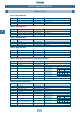
Refrigerant Pipe Installation Additional Refrigerant Charging Additional refrigerant charging amount reference chart Unit (kg) Actual piping length (m) Pipe size (Liquid pipe) Ø22.2 Actual piping length (m) Ø6.4 Ø9.5 Ø12.7 Ø15.9 Ø19.0 1 0.030 0.065 0.115 0.190 2 0.060 0.130 0.230 0.380 3 0.090 0.195 0.345 4 0.120 0.260 5 0.150 6 0.180 7 Pipe size (Liquid pipe) Ø6.4 Ø9.5 Ø12.7 Ø15.9 Ø19.0 Ø22.2 0.290 0.420 31 0.930 2.015 3.565 5.890 8.990 13.020 0.580 0.
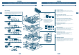
Trial Operation Procedure and Summary of Trial Operation Outline of procedure For a trial operation, follow the procedure below. Check before trial operation [ Check the basic items, especially installation work. Ensure you write the check results in the check lists 1 and 2. Implementation of trial operation check [ Implement check in sequence according to each flowchart of trial operation procedure.
Trial Operation Procedure and Summary of Trial Operation Trial operation check After “Check before trial operation”, implement a trial operation in the following procedure. (Turn the power switch on and the crank case heater for 12 hours before a trial operation will be completed.) Check the trial operation for each indoor unit. When multiple indoor units are concurrently operated check for misconnection, etc. of the refrigerant pipe and control wiring, errors can occur.
Trial Operation Procedure and Summary of Trial Operation (3) Cooling operation check Start Set the operation mode to COOL by pushing the operation switch for 5 seconds or more, and then check “L” is displayed. Trial operation from outdoor unit is also available. Check each indoor unit consecutively. Is there cool air discharge? No [ This air conditioner is attached with reactivation delay timer, so the operation restarts 2 minutes 30 seconds after it stopped.
Trial Operation Procedure and Summary of Trial Operation NOTE 1: Criteria for indoor air inlet/outlet temperature difference After operation for a minimum of 30 minutes in “COOL” mode, if temp. difference between the air inlet and air outlet of the indoor unit is 8°C or more – operation is normal. (In Max.
Trial Operation Automatic Address Automatic address (Between outdoor unit and indoor unit) When turning the power on for the first time after the air conditioner has been installed, automatic address starts. Usually, the automatic address takes time approx. 3 to 5 minutes after the power is on. However, in some cases, it may take Max. 20 minutes. Cautions during automatic addressing 1. The air conditioner cannot be operated.
Trial Operation Service Support Function Check function for connection of refrigerant pipe and control transmission line This function is provided to check misconnection of the refrigerant piping and the control transmission line between indoor and outdoor units by the switch on interface P.C. board of the inverter type outdoor unit. However, be sure to check items described below before implementing this check function. 1.
Trial Operation Service Support Function Function to start/stop (ON/OFF) indoor unit from outdoor unit A function to start/stop the following indoor units by switch operation on the interface P.C. board is provided. No. Function Outline Clear setup (1) Trial cooling operation The modes of all the connected indoor units are collectively changed to trial cooling operation modes. [Setup] Push SW04 for 2 seconds or more under condition of SW01 “2”, SW02 “5”, SW03 “1”.
Trial Operation Service Support Function (1) Trial cooling operation function This function is to change the modes of all the indoor units connected to an identical system collectively to trial cooling operation modes using the switch on interface P.C. board of the inverter type outdoor unit. Operation procedure Power ON 7 Segment LED 7 Segment LED Set SW01 on the interface P.C. board of the inverter outdoor unit to 2 , SW02 to 5, and SW03 to 1.
Trial Operation Service Support Function (2) Collective start/stop (ON/OFF) function This function is to start/stop (ON/OFF) the indoor units connected to an identical system collectively using the switch on the interface P.C. board of the inverter outdoor unit. Operation procedure Power ON If an alarm has been already displayed as SW01 1, SW02 1, SW03 1, return the status to normal according to Troubleshooting, and then execute a trial operation. Set the operation mode of the remote controller.
Trial Operation Service Support Function (3) Individual start/stop (ON/OFF) function This function is to start/stop (ON/OFF) the indoor units connected to an identical system individually using the switch on interface P.C. board of the inverter outdoor unit. Set SW01 to “16”, and SW02 and SW03 to the indoor unit to be operated. (See * in the following table) The set indoor units to operate alone.
Trial Operation Service Support Function Alarm clear function 1) Clearing of check code on remote controller This function releases ALL STOP lock status of the outdoor units (whole system) connected with the indoor unit, and restarts the operation. ( Restarts alarm detection.) CHECK button CHECK button Main remote controller RBC-SR1-PE Remote controller RBC-SR2-PE Push “CHECK” button of the remote controller for 3 seconds or more.
Trial Operation Service Support Function 3) Clearing of check code alarm by resetting power source Be sure to reset both power sources of outdoor/indoor units. Both power OFF Turn on power of the outdoor unit first, then indoor units. NOTE: Even if the lock alarm related to the indoor unit is cleared by resetting power source of the outdoor unit, ALL STOP lock status of whole system is not released.
Trial Operation Service Support Function Pulse Motor Valve (PMV) manual "FULL OPEN" function in the indoor unit With switch operation on interface P.C. board of the inverter outdoor unit, this function allows manual opening of the Pulse Motor Valve (PMV) in all the indoor units for 2 minutes. Usually, turning on power of the indoor unit once fully closes the PMV of the indoor unit.
Replacing the Compressor Refrigerant Recovery Method Refrigerant Recovery Method for a Failed Outdoor Unit When multiple outdoor units are connected in a system, the refrigerant can be recovered from the outdoor unit to be repaired by performing the reclaim operation to a functional outdoor unit. * NOTE 1: The refrigerant recovery ratio changes according to the outside temp., etc. After reclaim operation, recover the remaining gas using a recovery device, etc.
Replacing the Compressor Refrigerant Recovery Method A-3) 10 minutes after the system has been activated, close the gas pipe and balance pipe service valves of the failed outdoor unit fully. A-4) Turn off the power source for all the outdoor units. A-5) Recover the remaining gas in the failed outdoor unit using a refrigerant recovery device. (Calculate the recovered refrigerant, and be sure to add the calculated amount of refrigerant after repair has completed.
Replacing the Compressor Refrigerant Recovery Method Explanatory Diagram: Modular Multi Service Valve Figure: Open/Close direction of service valve Valve closed Valve open Figure: Position of service valve 19 Balancing pipe service valve Liquid pipe service valve Gas pipe service valve 132
Replacing the Compressor Compressor Replacement Procedure Start Recover refrigerant according to page 130 Refrigerant Recovery Method when replacing compressor or by a refrigerant recovery device. Was refrigerant recovery work executed when replacing the compressor? Turn off power of the failed unit. Remove parts. Extract oil from compressor. Remove the failed compressor. Install the compressor. Check leakage of the failed unit. Vacuum the failed unit. Charge refrigerant. Open valves fully.
Replacing the Compressor Compressor Replacement Procedure After recovery of refrigerant is complete, turn off the power source, and replace the compressor according to the following method. [In case of removal of the compressor from the front side] 1. Outdoor units (Inverter and fixed-speed units) MM-A0280HT, MM-A0224HT, MM-A0280HX, MM-A0224HX Removing of parts • Remove the front painted panel. • Remove electrical parts cover. • Disconnect all wires connected to the electric parts box. Temp.
Replacing the Compressor Compressor Replacement Procedure Installation • Install the compressor in the reverse order of removing the compressor. NOTE: After installation, fully open the valve at bottom side of the compressor, using a hexagonal wrench. 4-way valve Check joint Vacuuming • Connect the vacuum pump to the check joint of the discharge and suction pipes, and operate the vacuum pump. • Perform vacuuming until the vacuum low-pressure gauge indicates 0.750 (mmHg).
Replacing the Compressor Compressor Replacement Procedure NOTE: Weight of the compressor is approx. 45kg. • Remove the nuts fixing the compressor. • Remove the compressor. Installation • Install the compressor in the reverse order of removing the compressor. NOTE: After installation, fully open the valve at bottom side of the compressor, using a hexagonal wrench. Vacuuming • Connect the vacuum pump to the check joint of the discharge and suction pipes, and operate the vacuum pump.
Replacing the Compressor Compressor Replacement Procedure Removing of compressor • Remove two discharge pipes, suction pipe, upper oil return piping, oil tank piping, and case bypass piping. (Same case for pulling out from the front side) NOTE: Take great care when removing the pipes with a brazing torch – if oil is remaining in the pipe, a flame may be emitted at the moment when the flux melts. • Loosen the flare nut at the bottom side of the compressor to remove the pipe.
Replacing the Compressor Compressor Replacement Procedure 2. Outdoor unit MM-A0160HX Removing of parts • Remove the front painted panel. • Remove electrical parts cover. • Disconnect all wires connected to the electric parts box, temp. sensor, pressure sensor, complete, 2-way valve, PMV, 4-way valve, etc.. • Remove the electric parts box. • Remove the rear painted panel. • Remove the crank case heater. • Remove the sound-proof blanket. • Remove the terminal cover of the compressor, and remove all wires.
Replacing the Compressor Compressor Replacement Procedure Installation • Install the compressor in the reverse order of removing of compressor. NOTE: After installation, fully open the valve at bottom side of the compressor, using a hexagonal wrench. Vacuuming • Connect the vacuum pump to the check joint of the discharge and suction pipes, and operate the vacuum pump. • Perform vacuuming until the vacuum low-pressure gauge indicates 0.750 (mmHg).
Exploded Views and Service Parts Outdoor Units MM-A0280HT, MM-A0280HX, MM-A0224HT, MM-A0224HX 20 140
Exploded Views and Service Parts Outdoor Units MM-A0280HT, MM-A0224HT, MM-A0280HX, MM-A0224HX Ref No 1 2 3 4 5 6 7 8 9 10 10 10 11 11 12 13 14 15 16 17 18 19 20 21 22 23 24 25 26 27 28 29 30 31 32 33 34 35 36 37 38 39 40 41 42 43 44 45 46 47 48 49 50 51 52 53 54 55 56 57 58 59 60 61 62 62 Part No 43A00020 43A00021 43A00022 43A00023 43A00024 43A00025 43A00026 43A00027 43A20004 43A41510 43A41511 43A41512 43A49004 43A49005 43A49006 43A49007 43A49008 43A46019 43A46020 43A46021 43A46022 43A46023 43A46024 43A460
Exploded Views and Serivce Parts Outdoor Units MM-A0160HX 49 8 2 31 9 4 48 46 30 1 28/29 6 27 3 44 10 5 45 26 50 43 35 34 33 57 52 53 39 12/13 7 23 56 11 47 51 32 18 41 55 36 20 19 14/15 16/17 37 42 22 21 40 54 24/25 38 20 142
Exploded Views and Serivce Parts Outdoor Units MM-A0160HX Ref No. Part No.
Exploded Views and Service Parts Outdoor Unit Electrical Parts Assembly MM-A0280HT, MM-A0224HT 1 2 9 8 25 27 13 12 6 4 13 35 28 26 23 14 3 32 19 17 23 20 11 15 34 10 22 24 5 30/31 7 29 MM-A0280HX, MM-A0224HX 8 9 1 2 MM-A0160HX 8 3 11 10 1 2 34 34 24 24 6 6 16 16 32 32 33 29 33 5 5 18 3 11 10 19 18 29 20 19 20 4 4 21 21 20 144
Exploded Views and Service Parts Outdoor Unit Electrical Parts Assembly MM-A0280HT, MM-A0224HT, MM-A0280HX, MM-A0224HX, MM-A0160HX Location Part No. No.
Exploded Views and Service Parts Indoor Units Built-In Duct – MM-B056, MM-B080, MM-B112, MM-B140 18 22 20 2 7 1 12 19 10 8 3 6 4 9 5 17 11 15 14 16 21 1 2 2 02 43A21009 FAN MOTOR (60W) 1 02 43121516 FAN MOTOR (100W) 02 43121528 FAN MOTOR (120W) 02 43121535 FAN MOTOR (140W) 03 43A44068 REFRIGERATION ASSEMBLY 03 43A44069 REFRIGERATION ASSEMBLY 03 43A44070 REFRIGERATION ASSEMBLY 03 43A44071 REFRIGERATION ASSEMBLY 04 43A50024 TEMP.
Exploded Views and Service Parts Indoor Units High Wall – MM-K042, MM-KR042, MM-K056, MM-KR056, MM-K080, MM-KR080 29 1 23 6 5 4 11 3 10 19 8 16 21 12 7 9 2 24 31 26 25 20 13 27 15 14 32 33 22 18 17 30 CROSS FLOW FAN 02 43A21016 FAN MOTOR (27W) 02 43A21017 FAN MOTOR (27W) 03 43A44072 REFRIGERATION ASSEMBLY 03 43A44073 REFRIGERATION ASSEMBLY 03 43A44074 REFRIGERATION ASSEMBLY 04 43A50027 TEMP. SENSOR – AMBIENT (TA) 1 1 1 05 43A50021 TEMP.
Exploded Views and Service Parts Indoor Units Built-In Slim Duct – MM-SB028 9 17 8 7 10 13 11 4 12 3 14 15 5 2 1 6 19 16 20 20 SB082 18 Ref No Part No 01 43A50006 TEMPERATURE SENSOR CLIP (TC) 2 02 43A20003 FAN MULTI-BLADE 2 03 43A22005 S FAN CASE 2 04 43A22006 S FAN CASE 2 05 43A21020 FAN MOTOR (34W) 1 1 Description 06 43A44063 REFRIGERATION ASSEMBLY 07 43A50023 TEMPERATURE SENSOR – AMBIENT (TA) 1 08 43A50019 TEMPERATURE SENSOR – GAS (TC1) 1 09 43A50020 TEMPERA
Exploded Views and Service Parts Indoor Units 2-Way Cassette – MM-TU028, MM-TU042, MM-TU056 14 20 19 21 15 10 13 11/12 11/12 9 8 1 18 3 16 23 5 22 28 28 4 6 16 5 7 2 24 22 23 17 25 26 TU056 Ref No Part No TU028 TU042 TU056 Part No 01 43A22007 BLOWER BASE ASSEMBLY 1 02 43020288 CROSS FLOW FAN 2 03 43A51002 FLOAT SWITCH 1 04 43A70008 PUMP ASSEMBLY 1 05 43020253 BEARING 2 06 43071019 DRAIN CONNECTION 1 07 43A70009 DRAIN HOSE 1 08 43A60025 TERMINAL ‘ABC PQ
Exploded Views and Service Parts Indoor Units 4-Way Cassette – MM-U056, MM-U080 1 27 6 4 5 3 2 23 24 7 15 14 16 8 26 25 13 9 19 22 17 18 21 12 10 20 Part No 1 1 15 43A50022 TEMP. SENSOR – LIQUID (TC2) 1 16 43A50023 TEMP.
Exploded Views and Service Parts Indoor Units 4-Way Cassette – MM-U112, MM-U140 1 5 6 4 3 2 27 7 23 24 15 14 16 8 13 25 26 19 22 17 9 18 21 20 10 01 43A70005 DRAIN HOSE ASSEMBLY 1 1 15 02 43A44064 REFRIGERATION ASSEMBLY 1 02 43A44065 REFRIGERATION ASSEMBLY 03 43A70006 DRAIN PUMP 1 1 18 43A46037 PULSE MOTOR VALVE - COIL 1 1 04 43A51002 FLOAT SWITCH 1 1 19 43A60012 TERMINAL 'E - L - N' 1 1 05 43A21019 FAN MOTOR (36W) 1 1 20 43A60002 TERMINAL 'ABC' 1 1 06
TOSHIBA AIR CONDITIONING www.toshiba-aircon.co.