
Service manual


Troubleshooting
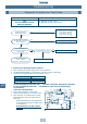
Diagnostic Procedure for Check Code
96
14
( *1) Oil tank peripheral circuit leakage/blockage check procedure
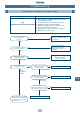
1. After resetting the power supply, start a trial operation.
2. Set SW01/SW02/SW03 on interface P.C. board to 1/16/1, respectively.
3. Check the 7 segment display of the interface P.C. board.
7 segment display
When operation has started "OL" "– –"
During detection of oil level "OL" "FF" or "Numeral"
Judgement result of oil level "OL" "AO" "A1" or "A4"
In case of judgment result “A0” “A1” Oil level is adequate. Resume the operation.
In case of judgment result “A4” Possibility of oil tank circuit leakage/blockage
is considered.
Check the following items.
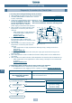
4. Start a trial operation, confirm that
AC220V–240V-power is on to SV3C valve.
5. After operation for several minutes check the
temperature at the secondary side of SV3C (A.)
When temperature is high (equivalent to
discharge temperature at (B)), valve is
not blocked.
If block
ed part is found, replace
the part.
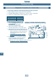
6. During operation, check whether leakage
occurs in the check valve (two positions)
of pipe connecting the oil tank and
compressor case. Check temperature either side of (C).
If leakage is found, replace the part.
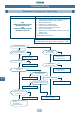
TK1 sensor
TK2
sensor
(A)
(B)
(C)
(C)
Valve
strainer
Oil
separator
Check joint
Strainer
Strainer
Strainer
Check
joint
Capillary
Capillary
Accumulator
Compressor
Balancing pipe valve
SV3C
SV3A
valve
SV3B
valve
Check
valve
Oil
removal
valve
Check
valve
Check
valve
Oil
tank