Cooper Bussmann Read and Retain for Future Reference 5073E-T Managed Ethernet Switch User Manual Version 1.
Cooper Bussmann 5073E-T Managed Ethernet Switch User Manual Interference Issues This equipment has been tested and found to comply with the limits for a Class A digital device, pursuant to Part 15 of the FCC rules. These limits are designed to provide reasonable protection against harmful interference in a commercial or industrial installation.
Cooper Bussmann 5073E-T Managed Ethernet Switch User Manual No part of this documentation or information supplied may be divulged to any third party without the express written consent of Cooper Bussmann/ELPRO Technologies. Products offered may contain software that is proprietary to Cooper Bussmann/ELPRO Technologies. The offer or supply of these products and services does not include or infer any transfer of ownership.
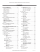
Cooper Bussmann 5073E-T Managed Ethernet Switch User Manual CONTENTS Chapter 1 - INTRODUCTION. . . . . . . . . . . . . . . . . . . 6 1.1 Module Identification. . . . . . . . . . . . . . . . . . . . . . 6 1.2 Mechanical Specifications. . . . . . . . . . . . . . . . . . 6 1.3 Order Information. . . . . . . . . . . . . . . . . . . . . . . . . 7 1.4 Hardware Features . . . . . . . . . . . . . . . . . . . . . . . 7 1.5 Software Features. . . . . . . . . . . . . . . . . . . . . . . . 8 1.6 Package Contents. . .
Cooper Bussmann 5073E-T Managed Ethernet Switch User Manual 6.7.3 Factory Defaults. . . . . . . . . . . . . . . . . . . . . . 72 6.7.4 Firmware Upgrade . . . . . . . . . . . . . . . . . . . . 72 6.7.5 Export/Import . . . . . . . . . . . . . . . . . . . . . . . . 73 6.7.6 Diagnostics. . . . . . . . . . . . . . . . . . . . . . . . . . 75 Ping . . . . . . . . . . . . . . . . . . . . . . . . . . . . 75 DDM. . . . . . . . . . . . . . . . . . . . . . . . . . . . 76 6.8 Troubleshooting. . . . . . . . . . . . . .
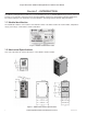
Cooper Bussmann 5073E-T Managed Ethernet Switch User Manual Chapter 1 - INTRODUCTION The 5073E-T Managed Ethernet Switch is a 7-Port 10/100 TX and 3-Port 10/100/1000T/Dual Speed SFP switch that provides a cost effective solution that meets the high reliability requirements demanded by industrial applications. The switch’s fiber port can extend the connection distance, increasing network elasticity and performance. 1.1 Module Identification The identification label is on the bottom of the 5073E-T Switch.
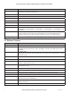
Cooper Bussmann 5073E-T Managed Ethernet Switch User Manual 1.3 Order Information Item Product Code Description Data Sheet Ethernet Switch 5073E-T 7+3G-Port Gigabit Managed Ethernet Switch with DIDO 10084 1.4 Hardware Features Feature Description Standard IEEE 802.3 10Base-T Ethernet IEEE 802.3u 100Base-TX/ FX IEEE802.3ab 1000Base-T IEEE802.3z Gigabit Fiber IEEE802.3x Flow Control and Back Pressure IEEE802.3ad Port Trunk with LACP IEEE802.1d Spanning Tree/ IEEE802.1w Rapid Spanning Tree IEEE802.
Cooper Bussmann 5073E-T Managed Ethernet Switch User Manual Feature Description Power Supply External Power Supply: DC 12–48 V, Redundant power DC 12–48 V and connective removable terminal block for master and slave power. Power Consumption 10.
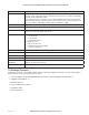
Cooper Bussmann 5073E-T Managed Ethernet Switch User Manual Feature Description Bandwidth Control Supports ingress packet filter and egress packet limit The egress rate control supports all of packet type and the limit rates are 100K to 102400 kbps (10/100), 100 K–256000 Kbps (1000). Ingress filter packet type combination rules are Broadcast/Multicast/Unknown Unicast packet, Broadcast/Multicast packet, Broadcast packet only and All of packet.
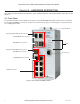
Cooper Bussmann 5073E-T Managed Ethernet Switch User Manual Chapter 2 - HARDWARE DESCRIPTION This chapter describes hardware specifications, ports, cabling information, and wiring installation information for the 5073E-T. 2.1 Front Panel The front panel includes seven 10/100 TX RJ-45 ports, three 10/100/1000T/ Mini-GBIC Combo ports, each with an RJ-45 and a 100/1000 SFP connector, one RS-232 connector (RJ-45 type) for connecting to a console (terminal or PC), and diagnostic LEDs.
Cooper Bussmann 5073E-T Managed Ethernet Switch User Manual 2.2 Top View The top panel of the 5073E-T Switch includes two terminal block connectors. One terminal block has two DC power inputs and one fault alarm, and the other has two digital inputs (DI) and two digital outputs (DO). Figure 4 Top Panel of 5073E-T Switch 2.3 LED Indicators The diagnostic LEDs are located on the front panel of the industrial switch and provide real-time information about the system.
Cooper Bussmann 5073E-T Managed Ethernet Switch User Manual LED Color State Description P7, P9, P10 (RJ-45) Green (Upper LED) On A network device is detected Blinking The port is transmitting or receiving packets from the TX device Off No device is attached On 1000 M Off 10/100 M On The SFP port is linking Blinking The port is transmitting or receiving packets from the TX device Off No device is attached On A network device is detected Blinking The port is transmitting or receiving
Cooper Bussmann 5073E-T Managed Ethernet Switch User Manual Chapter 3 - HARDWARE INSTALLATION This chapter describes how to install the 5073E-T Managed Ethernet Switch. 3.1 Installation Steps 1. Unpack the 5073E-T Ethernet Switch. The DIN rail is screwed onto the switch by default. To wall mount the 5073E-T Switch, refer to “3.3 Wall Mount Plate Mounting.” 2. Hang the switch on the DIN rail track or wall. 3. Power on the switch. For information on wiring the power, see “3.4 Wiring the Power Inputs.
Cooper Bussmann 5073E-T Managed Ethernet Switch User Manual 1. Insert the top of the DIN rail into the track. 2. Press the DIN rail into the track. 3. Check that the DIN rail is firmly secured to the DIN rail track. To remove the industrial switch from the track, reverse the steps above. 3.3 Wall Mount Plate Mounting Follow these steps to mount the switch using a wall mount plate. 1. Loosen the screws to remove the DIN rail from the 5073E-T Switch. 2.
Cooper Bussmann 5073E-T Managed Ethernet Switch User Manual 3.4 Wiring the Power Inputs Use the following steps below to insert the power wire. 1. Insert the DC power wires into the contacts for power 1 and power 2, as shown below. Power 1 Power 2 2. Tighten the wire-clamp screws to prevent the wires from coming loose. Power 1 Power 2 NOTE The wire gauge for the terminal block should be within the range 12–24 AWG. Rev Version 1.1 www.cooperbussmann.
Cooper Bussmann 5073E-T Managed Ethernet Switch User Manual 3.5 Wiring the Fault Alarm Contact The fault alarm contacts are in the middle of the terminal block connector, as shown in Figure 6. Insert the wires into the fault alarm contacts. After the wires are inserted, the switch detects the fault status of the power failure or port link failure, and then forms an open circuit. Figure 7 shows an application example for wiring the fault alarm contacts.
Cooper Bussmann 5073E-T Managed Ethernet Switch User Manual NOTE The SFP port and copper combo port cannot function at the same time. The SFP port has a higher priority than the copper port. If you insert the 1000 M SFP transceiver (which is connected to the remote device via fiber cable) into the SFP port, the connection of the accompanying copper port will link down.
Cooper Bussmann 5073E-T Managed Ethernet Switch User Manual Figure 11 Remove LC Connector b. Pull out the plastic handle to release the transceiver, and then grasp the tranceiver and pull it out. Figure 12 Pull Transceiver Out of SFP Port 18 www.cooperbussmann.com/wirelessresources Rev Version 1.
Cooper Bussmann 5073E-T Managed Ethernet Switch User Manual Chapter 4 - NETWORK APPLICATIONS This chapter provides sample applications for the Cooper Bussmann/ELPRO Technologies Industrial Ethernet Switches. Figure 13 Sample Application 4.1 Pro-Ring2se Application Pro-Ring2se is a new ring mechanism for the Cooper Bussmann/ELPRO Technologies Industrial Ethernet Switches. As Figure 15 shows, Pro-Ring2se can be constructed using two ports of the same type in each 5073E-T. Refer to “6.5.
Cooper Bussmann 5073E-T Managed Ethernet Switch User Manual Figure 15 Pro-Ring2se Connection Examples 20 www.cooperbussmann.com/wirelessresources Rev Version 1.
Cooper Bussmann 5073E-T Managed Ethernet Switch User Manual Chapter 5 - CONSOLE-BASED MANAGEMENT The 5073E-T Managed Ethernet Switch supports a CLI command interface that can be accessed by connecting the switch to a terminal or to a PC running a terminal emulator. This chapter describes how to connect and log onto the Console port (see Figure 3). Refer to “Appendix B - COMMAND SETS” for command descriptions and examples. 5.
Cooper Bussmann 5073E-T Managed Ethernet Switch User Manual 5.3 Logging onto the Console Interface 1. After connecting the 5073E-T Switch to the PC, turn on the PC. For connection instructions, see “5.1 Connecting to the Console Port.” 2. Run the terminal emulation program (for example, HyperTerminal or PuTTY) and configure its communication parameters to match the following default characteristics of the console port.
Cooper Bussmann 5073E-T Managed Ethernet Switch User Manual 5.4 CLI Management The system supports the console management CLI commands. After logging on to the system, you will see a command prompt. To enter the CLI management interface, type the “enable” command. See “Appendix B COMMAND SETS” for command descriptions and examples. Figure 20 CLI Command Interface Rev Version 1.1 www.cooperbussmann.
Cooper Bussmann 5073E-T Managed Ethernet Switch User Manual Chapter 6 - WEB-BASED MANAGEMENT The 5073E-T Switch has an embedded Web-based management utility that resides in flash memory on its CPU board. This utility offers advanced features that allow you to manage the switch from anywhere on the network through a standard browser such as Microsoft® Internet Explorer®. The utility supports Internet Explorer version 8.
Cooper Bussmann 5073E-T Managed Ethernet Switch User Manual 6.3 Web Page Overview The Web-based Management Utility uses a standard Web interface with the menu on the left. Click to expand a menu, and click to collapse a menu. You can also expand or collapse the entire menu tree by clicking Open All or Close All. Click a menu item to the page. The Help button at the bottom of each page displays additional information about page contents. Figure 21 Home Page - Web-based Management Utility 6.
Cooper Bussmann 5073E-T Managed Ethernet Switch User Manual Kernel Version Kernel software version. Device MAC Unique hardware address assigned by the manufacturer. System Time Current time on switch. Enable Location Alert Click to cause the fault LED on the switch to flash. Asset The Asset page allows you to change switch settings, including the system name, description, location, and contact information. Choose System-->General-->Asset to display this page.
Cooper Bussmann 5073E-T Managed Ethernet Switch User Manual Figure 24 CPU Load Average Page Loading Average Displays the CPU load statistics. Event Alarm Setting Select the Syslog checkbox if you want an alarm to be logged to the Syslog when the CPU load exceeds 90% utilization. Apply Click to apply the Event Alarm Setting. Refresh Click to reload the graph and table. 6.4.2 Time - SNTP To enable or disable the SNTP time function or set daylight savings time, choose System-->Time-->SNTP.
Cooper Bussmann 5073E-T Managed Ethernet Switch User Manual Figure 25 SNTP Page SNTP Client Enable or disable the SNTP function to get the time from the SNTP server. When enabled, the SNTP client uses the service from the SNTP server and the system time will follow the SNTP server. When disabled, local time is used without any SNTP server information.
Cooper Bussmann 5073E-T Managed Ethernet Switch User Manual Local Time Zone Conversion from UTC Time at 12:00 UTC EST - Eastern Standard CDT - Central Daylight -5 hours 7 am CST - Central Standard MDT - Mountain Daylight -6 hours 6 am MST - Mountain Standard PDT - Pacific Daylight -7 hours 5 am PST - Pacific Standard ADT - Alaskan Daylight -8 hours 4 am ALA - Alaskan Standard -9 hours 3 am HAW - Hawaiian Standard -10 hours 2 am Nome, Alaska -11 hours 1 am CET - Central European FWT
Cooper Bussmann 5073E-T Managed Ethernet Switch User Manual 6.4.3 Account - Admin Use the Admin page to change the login username and password for the Web-based Management utility to ensure access security. Choose System-->Account-->Admin to display this page. Figure 26 Admin Page User Name Type the new user name (the default is “admin”). New Password Type the new password. Confirm Password Re-type the new password. Apply Click to apply the settings. 6.4.
Cooper Bussmann 5073E-T Managed Ethernet Switch User Manual IP Address Enter a static IP address to the switch from the subnet address range that the network is using. If the DHCP Client option is enabled, the switch is configured as a DHCP client. The network DHCP server will assign the IP address to the switch and the switch displays it in this column. The default IP address is 192.168.1.88. You can also choose an IP address manually when the DHCP Client option is disabled.
Cooper Bussmann 5073E-T Managed Ethernet Switch User Manual Syslog Log To display the current system event log (Figure 29), choose System-->Syslog-->Log. Click Reload or press F5 to refresh the page to view the most recent events. Figure 29 Log Page Reload Reloads the current log. Clear Clears the log contents. 6.4.6 SNMP SNMP Agent Simple Network Management Protocol (SNMP) is the protocol developed to manage nodes (for example, servers, workstations, routers, switches and hubs) on an IP network.
Cooper Bussmann 5073E-T Managed Ethernet Switch User Manual Figure 30 SNMP Agent Configuration Agent Mode Select the SNMP version (V1/V2c or V3) that you want to use. And then click Apply to switch to the selected SNMP version mode. SNMP V1/V2c Community Allows you to define the new community string set and remove the unwanted community string. Community String Enter the name string. Privilege Read Only—Enables requests accompanied by this community string to display MIBobject information.
Cooper Bussmann 5073E-T Managed Ethernet Switch User Manual • Digital input trap • Topology change trap Figure 31 SNMP - Trap (Trap Manager) Server IP Enter the IP address of the trap manager. Community Enter the community string for the trap station. Trap Version Select the SNMP trap version type—v1 or v2c. Add Click to apply the settings. Remove To remove the community string, select the community string listed in the current manager’s field and click Remove.
Cooper Bussmann 5073E-T Managed Ethernet Switch User Manual management information items that can be accessed by an SNMPv3 entity. A context is identified by the SNMPv3 engine ID value of the entity hosting the management information (this can be found in System-->SNMP-->Agent) and a context name that identifies the specific context. An item of management information may exist in more than one context. An SNMP entity potentially has access to many contexts.
Cooper Bussmann 5073E-T Managed Ethernet Switch User Manual Use the Group tab to configure the SNMPv3 group table The group name created in this tab is associated with the user ID. Both the group name and the user ID are used as parameters to create entries in the access table that appears in the Access tab. Figure 34 SNMPv3 Group Tab 36 Current Group Content List of existing groups (and their associated user IDs). To remove a group, select the group and click Remove.
Cooper Bussmann 5073E-T Managed Ethernet Switch User Manual Use the Access tab to configure the SNMPv3 access table. The entries in this table define different access profiles. Each access profile can be identified by its context prefix and group name. An access profile is associated with a security level, context matching rule, and names of read, write, and modify MIB views. An MIB view can be created in the MIB View tab.
Cooper Bussmann 5073E-T Managed Ethernet Switch User Manual Add Adds the new access profile. Remove Removes the access profile selected in the Current Access Tables list. Use the MIB View tab to configure the management information base (MIB) table. Figure 36 SNMPv3 MIB View Tab Current MIB Tables Lists the existing MIB views. View Name Enter the name of the MIB view to be added (or removed).
Cooper Bussmann 5073E-T Managed Ethernet Switch User Manual Figure 37 System Alert - Relay Alarm (Fault Relay Alarm) Power Failure Setting Select the checkbox if you want the fault LED indicator on the panel to turn on when power fails. Port Link Down/ Broken Setting Select the port checkbox if you want the fault LED on the panel to turn on when the port link is down or broken. Apply Click to apply the setting. System Alert Event If the Syslog Mode is enabled on the Syslog Configuration page (see “6.
Cooper Bussmann 5073E-T Managed Ethernet Switch User Manual System Restart When enabled, the system will issue an alert to the system log server when the device executes a cold start. It may take a minute after the cold start before the event appears in the system log server. Power Status When enabled, the system will issue an alert to the system log server when input power to the switch becomes unstable.
Cooper Bussmann 5073E-T Managed Ethernet Switch User Manual Figure 40 Digital Output To set digital input and digital output triggers, choose System-->System Alert-->DIDO to display the following page. Figure 41 Digital Input/Output Trigger Setting Digital Input Setting Rev Version 1.1 Enabling DI0 makes the first digital input available. Enabling DI1 makes the second digital input available. www.cooperbussmann.
Cooper Bussmann 5073E-T Managed Ethernet Switch User Manual Digital Input Choose the transition type to trigger DI0 or DI1: • Low-->High—When this option is selected, DI0/DI1 will only report the status when the voltage of the external device changes from low to high. • High-->Low—When this option is selected, DI0/DI1 will only report the status when the voltage of the external device changes from high to low.
Cooper Bussmann 5073E-T Managed Ethernet Switch User Manual Figure 42 DHCP Server Configuration DHCP Server Enable or disable the DHCP server function on the switch. When enabled, the switch will be the DHCP server on your local network. Start IP Address Enter the IP address that is the beginning of the dynamic IP address range. For example, if the dynamic IP address is between 192.168.1.100 and 192.168.1.200, the start IP address would be 192.168.1.100.
Cooper Bussmann 5073E-T Managed Ethernet Switch User Manual Figure 44 IP Binding Apply Click to apply the setting. 6.5 Configure Menu 6.5.1 Port Port Configuration To configure the settings of each port to control the connection parameters, choose Configure-->Port->Configuration. The status of each port is listed at the bottom of the page. Figure 45 Port Configuration State 44 Allows you to enable or disable the port. When the port is disabled, it will not receive or transmit packets. www.
Cooper Bussmann 5073E-T Managed Ethernet Switch User Manual Speed/Duplex You can choose a port speed setting, or choose Auto Negotiation for the port to negotiate the speed. The port speed options vary depending on the port. For port 1-6 and port 8, the options are 100 FULL, 100 HALF, 10 FULL and 10 HALF. For port 7, 9, and 10, the options are 1000 FULL, 1000 HALF, 100 FULL, 100 HALF, 10 FULL, and10 HALF. NOTE The Speed/Duplex option applies only to the RJ-45 interface.
Cooper Bussmann 5073E-T Managed Ethernet Switch User Manual Figure 47 Port Statistics Port Port number. Type Displays the current speed of connection to the port. Link Current link status: Up—Link is operational. Down—Link is not operational. State State set on the Port Configuration page (see “6.5.1 Port”). When the state is disabled, the port will not transmit or receive packets. TX Good Packet Number of good packets transmitted via this port.
Cooper Bussmann 5073E-T Managed Ethernet Switch User Manual Figure 48 Port Alert Port Event For the Port Event menus to become available, the “Client Only” option in Syslog Configuration must be enabled (see “6.4.5 Syslog”). There are four port event options: • Link Up—The system will only issue a log message when the link-up event occurs for the port. • Link Down—The system will only issue a log message when the link-down event occurs for the port.
Cooper Bussmann 5073E-T Managed Ethernet Switch User Manual Figure 49 Rate Limit Egress Setting Allows you to set the egress rate limit (in kbps) for each port. Note that 1 Mbps is equal to 1024 kbps. The range is from 100 kbps to 102400 kbps (100 Mbps) for mega-ports, or 256000 kbps (250 Mbps) for giga-ports. Zero indicates no egress rate limit. Apply Click to apply the settings.
Cooper Bussmann 5073E-T Managed Ethernet Switch User Manual Ingress Limit Frame Type Select the frame type to be filtered: • • • • All Broadcast/Multicast/Flooded Unicast Broadcast/Multicast Broadcast only Broadcast/Multicast/Flooded Unicast, Broadcast/Multicast, and Broadcast only types are only for ingress frames. The egress rate only supports the “All” type. Ingress Set the ingress rate limit, in kbps. (One Mbps is equal to 1024 kbps.
Cooper Bussmann 5073E-T Managed Ethernet Switch User Manual Type Select the trunk group type for the port (Static or LACP). • Static—When Static is selected as the trunk group type for a port, the port belongs to the trunk group whose ID is selected in Group ID drop down menu for that port. Static trunk groups are only allowed to aggregate traffic in two to four ports. When ports belong to a static trunk, the traffic in the trunk group is distributed evenly among the ports belonging to the trunk group.
Cooper Bussmann 5073E-T Managed Ethernet Switch User Manual RSTP Settings The Spanning Tree - RSTP Settings page provides the bridge and port configuration interface for RSTP. You can assign a higher or lower priority to each port. When RSTP is enabled, the port with the higher priority is in the forwarding state and other ports are blocked to make certain there is no loop in the LAN. To configure RSTP settings, choose Configure-->Spanning Tree-->RSTP Settings.
Cooper Bussmann 5073E-T Managed Ethernet Switch User Manual P2P The rapid state transitions possible within RSTP depend on whether the port concerned can only be connected to a specific bridge (it is served by a point-to-point LAN segment), or can be connected to two or more bridges (it is served by a shared medium LAN segment). This function allows the P2P (point-to-point) status of the link to be manipulated administratively.
Cooper Bussmann 5073E-T Managed Ethernet Switch User Manual Root Port The port used to connect to the Root switch. This port has the lowest root path cost. Root Path Cost Indicates how suitable this port is as a node for the Spanning Tree topology. A lower value indicates greater suitability. Max Age Time The number of seconds that this device waits before checking to see if it should change to a different state.
Cooper Bussmann 5073E-T Managed Ethernet Switch User Manual Primary Port Secondary port Any two ports from a switch can be chosen to build the ring topology. NOTE Although any two ports of switch can be chosen for this option, the selected ports must be equipped with the same speed and the same type of interface as other switches in the same ring. For example, if port 1 and port 2 with a speed of 10/100 TX are chosen, the ring ports of other switches in the same ring must be 10/100 TX.
Cooper Bussmann 5073E-T Managed Ethernet Switch User Manual Message Description Leave Group A message sent by a host to the querier to indicate that the host has quit being a member of a specific multicast group. IGMP Snooping If the switch supports IP multicast, you can enable the IGMP protocol. To display this page, choose Configure-->Multicast Support-->IGMP Snooping. When IGMP Snooping is enabled, the IGMP snooping information displays on the page. IP multicast addresses range from 224.0.0.
Cooper Bussmann 5073E-T Managed Ethernet Switch User Manual To configure filtering, choose Configure-->Multicast Support-->Static Filtering. Figure 57 Static Filtering IP Address Assign a multicast group IP address in the range 224.0.0.0 to 239.255.255.255. Member Ports Select the port checkbox to include the port as a member in the specified multicast group IP address. Add Click to add the address to the multicast filtering list. Delete Click to remove a selected filter. 6.5.
Cooper Bussmann 5073E-T Managed Ethernet Switch User Manual LLDP Protocol Enable or disable the LLDP function. LLDP Interval Set the interval (in seconds) for advertising the switch information to other nodes. Sync Time Enables or disables switch clock synchronization using LLDP. Apply Click to apply the settings. LLDP Neighbors The LLDP Neighbors page displays information about the port neighbors discovered using the LLDP protocol. To display this page, choose Configure-->LLDP-->LLDP Neighbors.
Cooper Bussmann 5073E-T Managed Ethernet Switch User Manual MAC Address Configuration Set the aging time (in seconds) for the MAC address table. Select the Auto Flush checkbox if you want the MAC address table to be erased if the port link fails. Security Enable or disable secure learning mode. When enabled, only static MAC addresses are learned; all other frames are dropped.
Cooper Bussmann 5073E-T Managed Ethernet Switch User Manual 802.1Q VLAN Mode—If you choose 802.1Q VLAN mode (Figure 62), you can see the link type, untagged VID, and tagged VID information of each port. Figure 62 VLAN Configuration - 802.1Q VLAN Operation Mode Select the VLAN operation mode, or disable VLAN. The following fields appear when you choose 802.1Q VLAN mode.
Cooper Bussmann 5073E-T Managed Ethernet Switch User Manual • IQ Trunk Link—This link type only supports multiple tagged VIDs. The IQ trunk link is a segment that provides the link path for one or more VLAN‑aware devices (switches). A trunk port, connected to the trunk link, has an understanding of tagged frame, which is used for communication among VLANs across switches. Which frames of the specified VIDs will be forwarded depends on the values filled in the Tagged VID column field.
Cooper Bussmann 5073E-T Managed Ethernet Switch User Manual Port Based VLAN Mode—Port Based VLAN mode provides a simple way to create a VLAN. To create a new port based VLAN, first choose “Port Based” in the Operation Mode field (see Figure 63), and then click Add. The screen now looks like Figure 64. Simply name the VLAN, assign a VLAN ID, and select the ports to be included in the VLAN.
Cooper Bussmann 5073E-T Managed Ethernet Switch User Manual Figure 64 VLAN Configuration - Port-based VLAN (Step 2) Operation Mode Select the VLAN operation mode or disable VLAN. The following fields appear when you choose Port Based VLAN mode. Group Name Assign a name to the VLAN. VLAN ID Assign an identifier to the VLAN. Add To add a port to the VLAN, click the port in the left port column and click Add. The port appears in the right column, indicating that it is in the VLAN.
Cooper Bussmann 5073E-T Managed Ethernet Switch User Manual 6.5.10 QoS Quality of Service (QoS) allows you to assign a priority to various applications, users, or data flows, or guarantee a specific level of performance to a data flow. QoS guarantees are important if network capacity is insufficient, particularly for real-time streaming multimedia applications, such as voice-over-P and video teleconferencing. These applications often require a fixed bit rate.
Cooper Bussmann 5073E-T Managed Ethernet Switch User Manual Port Priority When the QoS Mode on the QoS - Global Settings page is set to “Port Based,” you can set the queuing policy for each port. To display the QoS Port Priority page, choose Configure-->QoS-->Port Priority. Figure 67 Port Priority Priority Select a priority level (high, middle, low, or lowest). Apply Click to apply the settings.
Cooper Bussmann 5073E-T Managed Ethernet Switch User Manual COS Priority Select a COS priority level (high, middle, low, or lowest). COS Port Default Assign a default priority value to each port. A default priority is considered and determined by the ingress port when an ingress packet has no VLAN tag. Apply Click to apply the setting. DSCP Mapping to Queue This page allows you to set the default priority for incoming packets that do not have a priority assigned to them.
Cooper Bussmann 5073E-T Managed Ethernet Switch User Manual Figure 70 Mirroring Destination Port Set which switch port will be responsible for collecting the data that was duplicated from the source port. Source Port Set which switch port will have its data duplicated and sent to the destination port. Apply Click to apply the settings. 6.6 Security Menu The Security function allows you to block unauthorized clients. 6.6.
Cooper Bussmann 5073E-T Managed Ethernet Switch User Manual IP Security Mode Enable or disable IP security. When security is enabled, the fields on this page become active. Enable Web Management When this checkbox is selected, any device whose IP address matches one of the 10 IP addresses in the Security IP1–P10 table (see the next section) will be given permission to access this switch via HTTP service.
Cooper Bussmann 5073E-T Managed Ethernet Switch User Manual 6.6.2 802.1X/Radius The IEEE authentication specification 802.1X prevents the client from accessing a wireless access point or wired switch until it provides security information, such as a user name and password, which is verified by an authentication server (for example, a RADIUS server). 802.1X/Radius Configuration Use the 802.1x/Radius - Configuration page to configure a RADIUS server. To display this page, choose Security-->802.
Cooper Bussmann 5073E-T Managed Ethernet Switch User Manual Server Timeout Set the number of seconds that the switch waits for a server response to an authentication request. Max Requests Set the number of authentications that must time-out before authentication fails and the authentication session ends. Re-Auth period Set the number of seconds after which connected clients must be re-authenticated. Apply Click to apply the settings. 802.1X/Radius Port Setting You can configure the 802.
Cooper Bussmann 5073E-T Managed Ethernet Switch User Manual Figure 75 802.1X Radius - Port Status 6.6.3 MAC Filtering To block an unauthorized MAC address by switch, choose Security-->MAC Filtering. The MAC blacklist shows the list of MAC addresses that are currently blocked. Figure 76 MAC Filtering 70 MAC Address Enter a MAC address that you want add or delete from the MAC blacklist. Addresses on the blacklist will be blocked by the switch.
Cooper Bussmann 5073E-T Managed Ethernet Switch User Manual 6.6.4 Port Security To block (or unblock) a MAC address by port, choose Security-->Port Security. Figure 77 Port Security MAC Address Enter a MAC address that you want add or delete from the Port Security List. Addresses on this list will be allowed access to the port.. Port No. Select a port number. Add, Delete Click Add to add the address to the Port Security List, or click Delete to remove the address from the Port Security List. 6.
Cooper Bussmann 5073E-T Managed Ethernet Switch User Manual 6.7.2 Restart Device To reboot the switch, choose Maintenance-->Restart Device, and then click Reboot. Figure 79 Restart Device 6.7.3 Factory Defaults To reset the switch to its default configuration, choose Maintenance-->Factory Defaults, and then click Reset. You have the option of keeping the current IP address, username, and password settings. Figure 80 Factory Defaults 6.7.
Cooper Bussmann 5073E-T Managed Ethernet Switch User Manual TFTP Server IP Address Enter your TFTP server IP address. Firmware File Name Enter the name of the firmware image file to be updated. Upgrade Click to upgrade to the new firmware. The Web tab allows you to use a browser to update the firmware on your hard drive. This function is not supported by the Google Chrome browser. Figure 82 Firmware Upgrade - Web Browse Click to locate the new firmware image file.
Cooper Bussmann 5073E-T Managed Ethernet Switch User Manual System/Account – Admin Settings: • User Name • New Password • Confirm Password NOTE The 5073E-T Web server works best when used with Internet Explorer. The Google Chrome browser does not support exporting to or importing from a local computer (a computer connected to the switch). To export a configuration file to a TFTP server, enter the TFTP server IP address and the backup file name, and then click Backup in the upper part of the Export tab.
Cooper Bussmann 5073E-T Managed Ethernet Switch User Manual To import a configuration file that was exported to a TFTP server, enter the TFTP server IP address and the backup file name, and then click Restore in the upper part of the Import tab. To import a configuration file that was exported to a local computer connected to the 5073E-T Switch, use the Browse button to locate the backup file, and then click Restore in the bottom part of the Import tab.
Cooper Bussmann 5073E-T Managed Ethernet Switch User Manual DDM To configure digital diagnostic monitoring (DDM) functions, choose Maintenance-->Diagnostics-->DDM. DDM enables you to monitor real-time parameters of the SFP ports and set whether the port logs alarm events to the Syslog on the switch. Figure 86 Diagnostics - DDM Syslog When selected, the port will log alarm events to the local Syslog on the switch. Port No. Select this checkbox to display the SFP module information.
Cooper Bussmann 5073E-T Managed Ethernet Switch User Manual describe common problems you may encounter and indicate where you can find solutions. 4. If the power indicator does not turn on when the power cord is plugged in, you may have a problem with power cord. Check for loose power connections, power losses, or surges at the power outlet. If you still cannot resolve the problem, contact your local dealer for assistance. 5.
Cooper Bussmann 5073E-T Managed Ethernet Switch User Manual Appendix A - RJ-45 PIN ASSIGNMENT The UTP/STP ports will automatically detect fast Ethernet (10Base-T/100Base-TXconnections), or Gigabit Ethernet (10Base-T/100Base-TX/1000Base-T connections). Auto MDI/MDIX means that the switch can connect to another switch or workstation without changing straight-through or crossover cabling. See the figures in this appendix for straight through and crossover cable schematics.
Cooper Bussmann 5073E-T Managed Ethernet Switch User Manual 10/100/1000Base-TX Pinouts Figure 89 shows the 10/100/1000 Ethernet RJ-45 pinouts. Figure 89 10/100/1000 Ethernet RJ-45 Pinouts 10/100/1000Base-TX Cable Schematic Figure 90 Straight-through Cable Schematic Figure 91 Crossover Cable Schematic Rev Version 1.1 www.cooperbussmann.
Cooper Bussmann 5073E-T Managed Ethernet Switch User Manual Appendix B - COMMAND SETS This appendix describes the command sets for the 5073E-T Managed Ethernet Switch. The commands are associated with a user level, described in the following key. E = User EXEC P = Privileged EXEC G = Global configuration V = VLAN database I = Interface configuration 802.1x Commands CLI Commands Level Description Example 8021x enable G Enable IEEE802.1x function.
Cooper Bussmann 5073E-T Managed Ethernet Switch User Manual CLI Commands 8021x misc servertimeout Level Description Example G Use the 802.1x misc server timeout global configuration command to set the server timeout. switch>enable switch#configure switch(config)#8021x misc servertimeout 20 G Use the 802.1x misc max request global configuration command to set the MAX requests. switch>enable switch#configure switch(config)# 8021x misc maxrequest 3 G Use the 802.
Cooper Bussmann 5073E-T Managed Ethernet Switch User Manual CLI Commands tftp Level Description G Get configuration from TFTP server. Need to specify the IP address of the TFTP server and the file name of image. [server IP] restore Defaults/Example switch>enable switch#configure switch(config)#tftp 192.168.1.120 restore 123.bin [file name] CLI Commands CLI Commands Level Description Example enable E Enter Privileged EXEC mode. switch>enable quit E Logout command line shell.
Cooper Bussmann 5073E-T Managed Ethernet Switch User Manual CLI Commands dhcpserver gateway Level Description Example G Configure gateway for DHCP clients. switch>enable switch#configure switch(config)#dhcpserver gateway 192.168.1.254 G Configure DNS IP address for DHCP clients. switch>enable switch#configure switch(config)#dhcpserver dnsip 192.168.1.1 G Configure lease time (hours.
Cooper Bussmann 5073E-T Managed Ethernet Switch User Manual CLI Commands no fault-relay Level Description G Example Disable fault relay alarm function. switch>enable switch#configure switch(config)#no fault-relay Description Example IGMP Commands CLI Commands Level igmp enable G Enable IGMP snooping function. switch>enable switch#configure switch(config)#igmp enable igmp query G Configure IGMP query mode.
Cooper Bussmann 5073E-T Managed Ethernet Switch User Manual IP Security Commands CLI Commands Level Description Example security enable G Enable IP security function. switch>enable switch#configure switch(config)#security enable security http G Enable IP security of HTTP server. switch>enable switch#configure switch(config)#security http security telnet G Enable IP security of telnet server.
Cooper Bussmann 5073E-T Managed Ethernet Switch User Manual CLI Commands no ip dhcp Level Description G Example Disable DHCP client function of switch. switch>enable switch#configure switch(config)#no ip dhcp Description Example LLDP Commands CLI Commands Level lldp enable G Enable LLDP function. switch>enable switch#configure switch(config)#lldp enable lldp interval G Configure LLDP interval.
Cooper Bussmann 5073E-T Managed Ethernet Switch User Manual CLI Commands Level Description Example no mac-address-table G Remove dynamic entry of MAC address table. switch>enable switch#configure switch(config)#no mac-address-table agingtime G Configure MAC address table aging time. switch>enable switch#configure switch(config)#agingtime 30 G Auto flush MAC address table when ports link is down.
Cooper Bussmann 5073E-T Managed Ethernet Switch User Manual Ping Command CLI Commands ping Level Description E Ping function. Example switch>ping 192.168.1.1 [ip] Port Control Commands CLI Commands interface fastEthernet Level Description Example G Choose the port for modification. switch>enable switch#configure switch(config)#interface fastEthernet 2 I Use the state interface configuration command to specify the state mode of operation for Ethernet ports.
Cooper Bussmann 5073E-T Managed Ethernet Switch User Manual CLI Commands Level Description alias I Set port alias name. switch>enable switch#configure switch(config)#interface fastEthernet 2 switch(config-if)#alias 1111 I Show interface configuration status.
Cooper Bussmann 5073E-T Managed Ethernet Switch User Manual CLI Commands Level Description Example no mac-address-table static hwaddr I Remove an entry from the MAC address table of interface (static). switch>enable [HW-Addr] switch#configure switch(config)#interface fastEthernet 2 switch(config-if)#no mac-addresstable static hwaddr 000012345678 Port Statistics Commands CLI Commands Level Description Example show interface accounting I Show interface statistic counter.
Cooper Bussmann 5073E-T Managed Ethernet Switch User Manual CLI Commands pro-ring2se control-vlan Level Description Example G Configure control VLAN. switch>enable switch#configure switch(config)# pro-ring2se controlvlan 100 G Configure protect VLAN. switch>enable switch#configure switch(config)# pro-ring2se protectvlan 200 show pro-ring2se P Show Pro-Ring2se configuration. switch>enable switch# show pro-ring2se no pro-ring2se G DisablePro-Ring2se.
Cooper Bussmann 5073E-T Managed Ethernet Switch User Manual RSTP Commands CLI Commands Level Description Example rstp enable G Enable RSTP. switch>enable switch#configure switch(config)#rstp enable rstp priority G Configure RSTP bridge priority parameter. switch>enable switch#configure switch(config)#rstp priority 4096 G Configure RSTP max age parameter. switch>enable switch#configure switch(config)#rstp max-age 6 G Configure RSTP hello time parameter.
Cooper Bussmann 5073E-T Managed Ethernet Switch User Manual Save Configuration Command CLI Commands write memory Level P Description Example Save user configuration into permanent memory (flash ROM). switch>enable switch#write memory SFP Monitor Command CLI Commands show ddm Level Description P Show temperature alarm information. Example switch>enable switch# show ddm SNMP Commands CLI Commands Level Description Example snmp agent-mode [v1v2c|v3] G Select the agent mode of SNMP.
Cooper Bussmann 5073E-T Managed Ethernet Switch User Manual SNTP Commands CLI Commands Level Description Example sntp enable G Enable the SNTP function. switch>enable switch#configure switch(config)#sntp enable sntp ip G Set the SNTP server IP address. If the SNTP function is inactive, this command cannot be applied. switch>enable switch#configure switch(config)#sntp ip 192.168.1.1 G Set timezone index, use “show sntp timzezone” command to get more information about the index number.
Cooper Bussmann 5073E-T Managed Ethernet Switch User Manual CLI Commands system description Level Description G Set switch system description string. switch>enable switch#configure switch(config)#system description xxx G Set switch system contact window string. switch>enable switch#configure switch(config)#system contact xxx E Show system information.
Cooper Bussmann 5073E-T Managed Ethernet Switch User Manual CLI Commands Level Description Example show event P Show event selection. switch>enable switch#show event no event system-restart syslog G Disable device restart event type. switch>enable switch#configure switch(config)#no event systemrestart syslog no event authenticationfailure syslog G Disable Authentication failure event type.
Cooper Bussmann 5073E-T Managed Ethernet Switch User Manual Trunk Commands CLI Commands aggregator priority Level Description Example G Set port group system priority. switch>enable switch#configure switch(config)#aggregator priority 22 G [GroupID] [Port-list] Assign a trunk group with LACP active.
Cooper Bussmann 5073E-T Managed Ethernet Switch User Manual VLAN Commands CLI Commands Level Description Example vlan database P Enter VLAN configure mode. switch>enable switch#vlan database vlanmode V Set switch VLAN mode. switch>enable switch#vlan database [portbase| 802.1q | disable| gvrp] switch(vlan)#vlanmode or switch(vlan)#vlanmode or switch(vlan)#vlanmode or switch(vlan)#vlanmode portbase 802.
Cooper Bussmann 5073E-T Managed Ethernet Switch User Manual CLI Commands vlan 8021q port [PortNumber] Level Description V trunk-link tag [TaggedVID List] vlan 8021q port [PortNumber] V hybrid-link untag [UntaggedVID] Assign a trunk link for VLAN by port. If the port belongs to a trunk group, this command cannot be applied. switch>enable switch#vlan database Assign a hybrid link for VLAN by port. If the port belongs to a trunk group, this command cannot be applied.
Cooper Bussmann 5073E-T Managed Ethernet Switch User Manual CLI Commands show vlan [GroupID] Level Description V Show VLAN information. or show vlan no vlan [GroupID] Example switch>enable switch#vlan database switch(vlan)#show vlan 2 V Delete port base group ID. switch>enable switch#vlan database switch(vlan)#no vlan 2 100 www.cooperbussmann.com/wirelessresources Rev Version 1.
Cooper Bussmann 5073E-T Managed Ethernet Switch User Manual Appendix C - GLOSSARY Term Definition AWG American wire gauge (AWG), also known as the Brown & Sharpe wire gauge, is a standardized wire gauge system used predominantly in the United States and Canada for the diameters of round, solid, nonferrous, electrically conducting wire. Bandwidth The maximum data transfer speed available to a user through a network.
Cooper Bussmann 5073E-T Managed Ethernet Switch User Manual Term Definition IP Internet protocol. A set of rules used to send and receive messages across local networks and the Internet. IP Address A 32-bit number that identifies each sender or receiver of information that is sent across the Internet. An IP address has two parts: an identifier of a particular network on the Internet and an identifier of the particular device (which can be a server or a workstation) within that network.
Cooper Bussmann 5073E-T Managed Ethernet Switch User Manual Term Definition SNMP Simple Network Management Protocol (SNMP) is an Internet-standard protocol for managing devices on IP networks. Devices that typically support SNMP include routers, switches, servers, workstations, printers, modem racks and so on. It is used mostly in network management systems to monitor network-attached devices for conditions that warrant administrative attention.
Cooper Bussmann 5073E-T Managed Ethernet Switch User Manual Term Definition Wi-Fi Wireless Fidelity. An interoperability certification for wireless local area network (LAN) products based on the Institute of Electrical and Electronics Engineers (IEEE) 802.11 standard. 104 www.cooperbussmann.com/wirelessresources Rev Version 1.
Cooper Bussmann 5073E-T Managed Ethernet Switch User Manual Notes Rev Version 1.1 www.cooperbussmann.
Customer Assistance North America & Latin America 5735 W. Las Positas Suite 100 Pleasanton, California 94588 USA Telephone: +1 925 924 8500 elpro-sales@cooperindustries.com Technical Support: United States:+1 866 713 4409 Australasia.: +61 7 3352 8624 Other: +1 604 944 9247 Email: ELPRO-Support@cooperindustries.com Website: www.cooperbussmann.com/wireless Australasia Fax: +61 7 33528677 US Fax: +1 925 924 8502 Online Resources Visit www.cooperbussmann.