DOCUMENT 1025 REVISION B July 14, 2011 Instruction Manual Airside Guidance Sign AGS-LED 858 LED Series Sizes 1, 2, 3, 4 and 5 Cooper Industries Crouse-Hinds Division Airport Lighting Products 1200 Kennedy Road Windsor, CT 06095 Copyright © 2011 Cooper Technologies Company For Parts or Technical Service Call (860) 683-4300
DOCUMENT 1025 REV.
DOCUMENT 1025 REV. B Instruction Manual AGS-LED 858 LED Series Sizes 1, 2, 3, 4 and 5 2 Limited Product Warranty THE FOLLOWING WARRANTY IS EXCLUSIVE AND IN LIEU OF ALL OTHER WARRANTIES, WHETHER EXPRESS, IMPLIED OR STATUTORY, INCLUDING, BUT NOT BY WAY OF LIMITATION, ANY WARRANTY OF MERCHANTABILITY OR FITNESS FOR ANY PARTICULAR PURPOSE.
DOCUMENT 1025 REV. B Instruction Manual AGS-LED 858 LED Series Sizes 1, 2, 3, 4 and 5 3 Safety Notices This equipment is normally used or connected to circuits that may employ voltages which are dangerous and may be fatal if accidentally contacted by operating or maintenance personnel. Extreme caution should be exercised when working with this equipment. While practical safety precautions have been incorporated in this equipment, the following rules must be strictly observed: 3.
DOCUMENT 1025 REV. B Instruction Manual AGS-LED 858 LED Series Sizes 1, 2, 3, 4 and 5 4 Safety Symbols 4.1 Danger DANGER: DANGER 4.2 The hazard or unsafe practice will result in severe injury or death. Warning WARNING: WARNING 4.3 The hazard or unsafe practice could result in severe injury or death. Caution CAUTION: CAUTION 4.4 The hazard or unsafe practice could result in minor injury. Warning: Notice WARNING: NOTICE 4.5 Possibly dangerous situation, goods might be damaged.
DOCUMENT 1025 REV. B Instruction Manual AGS-LED 858 LED Series Sizes 1, 2, 3, 4 and 5 5 Test Equipment and Tools There is a wide variety of tools and equipment needed to safely and correctly perform airfield lighting equipment installation and maintenance. In addition to the obvious tools (screwdrivers, wrenches, etc.), there is a specialized equipment needed to do the job. Multimeter One of the most important pieces of test equipment is the Multimeter.
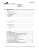
DOCUMENT 1025 REV. B Instruction Manual AGS-LED 858 LED Series Sizes 1, 2, 3, 4 and 5 6 Table of Contents 1 2 3 Revisions ............................................................................................................................... ii Limited Product Warranty .................................................................................................... iii Safety Notices ...............................................................................................................
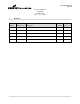
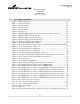
DOCUMENT 1025 REV. B Instruction Manual AGS-LED 858 LED Series Sizes 1, 2, 3, 4 and 5 7 List of Figures and Tables Figure 1. Single module sign ....................................................................................................... 20 Figure 2. Double module sign...................................................................................................... 21 Figure 3. Three module sign .................................................................................................
DOCUMENT 1025 REV. B Instruction Manual AGS-LED 858 LED Series Sizes 1, 2, 3, 4 and 5 8 General Information 8.1 General Description Crouse-Hinds Airport Lighting Products, “AIRSIDE” internally illuminated LED Taxiway and Runway Signs provide outstanding message visibility, day or night. White on Red and Yellow on Black and Black on Yellow color combinations may be ordered with any desired message. Signs are available as single or double faced and are provided with retro-reflective sign face.
DOCUMENT 1025 REV. B Instruction Manual AGS-LED 858 LED Series Sizes 1, 2, 3, 4 and 5 8.
DOCUMENT 1025 REV. B Instruction Manual AGS-LED 858 LED Series Sizes 1, 2, 3, 4 and 5 9 Installation WARNING: NOTICE Sign foundations/pad and their design are the responsibility of the installer and/or airport and recommendations/suggestions herein are for guidance only.
DOCUMENT 1025 REV. B Instruction Manual AGS-LED 858 LED Series Sizes 1, 2, 3, 4 and 5 d. The concrete foundation/pad should be not more than 1 inch above grade in or order der to maintain the 3 inch maximum overall height above grade to the point of frangibility per FAA Engineering Brief no. 79. See the Engineering Brief for acceptable grading around the foundation/pad. The foundation/pad pad must be level. e.
DOCUMENT 1025 REV. B Instruction Manual AGS-LED 858 LED Series Sizes 1, 2, 3, 4 and 5 Isolation Transformer should be placed on a brick in order to isolate the transformer from direct contact with metal. The Series Isolation Transformer secondary cable should then be inserted from inside the housing up the conduit elbow.
DOCUMENT 1025 REV. B Instruction Manual AGS-LED 858 LED Series Sizes 1, 2, 3, 4 and 5 10 Maintenance and Troubleshooting WARNING: WARNING 10.1 Remove Power Before Attempting Any Servicing. General Work on electrical circuits shoul should d be done only by a qualified electrician with a working knowledge of airfield lighting circuits. Trouble-shooting is accomplished by means of process of elimination.
DOCUMENT 1025 REV. B Instruction Manual AGS-LED 858 LED Series Sizes 1, 2, 3, 4 and 5 CAUTION: CAUTION Do not over tighten hex nut on stud retaining bridge rectifier. 8in-lbs max. (See Figure 18) Also, remover carriers from thermal pad adhesive surfaces before installing. WARNING: IMPORTANT When tightening cover screws, do not use power drivers as you may exceed the maximum torque of 75 in-lbs on the cover screws. DANGER: DANGER 10.
DOCUMENT 1025 REV. B Instruction Manual AGS-LED 858 LED Series Sizes 1, 2, 3, 4 and 5 PROBLEM POSSIBLE CAUSE CORRECTIVE ACTION (P.2) Sign will not light Input current is below or exceeds specification. (Input current is specified between 2.8 and 6.6 amps using a true RMS Ammeter. L858 Power Supply indicator RED LEDs D4 is ON, and D7 is OFF; Table 12) Adjust CCR current (See Tables 9-11 and/or replace isolation transformer with appropriate wattage for sign (see Tables 3-8). (P.
DOCUMENT 1025 REV. B Instruction Manual AGS-LED 858 LED Series Sizes 1, 2, 3, 4 and 5 PROBLEM POSSIBLE CAUSE CORRECTIVE ACTION MODULE(s) (See Sec 10.10) (P.10) Upon applying power, sign momentarily lights and then turns off. Incorrect LED Power Supply Circuit Board Switch Configuration Verify/Set Power Supply Board Switches and jumpers are set according to Table 1 (Ferro CCR) or Table 2 (Series CCR) (P.11) Upon applying power, sign momentarily lights and then turns off.
DOCUMENT 1025 REV. B Instruction Manual AGS-LED 858 LED Series Sizes 1, 2, 3, 4 and 5 10.3 Measuring Input Current (Signs Without Optional Power Switch) WARNING: WARNING Failure to turn off power to the sign and wait five minutes could result in severe injury or death. Turn off power to the sign by turning off the corresponding Constant Current Regulator (CCR) power. (WARNING: Wait five minutes after sign power is turned off to service the sign.
DOCUMENT 1025 REV. B Instruction Manual AGS-LED 858 LED Series Sizes 1, 2, 3, 4 and 5 Voltage is greater than 30-VDC, then you must w wait ait until the Power Supply Output Voltage drops below 30-VDC before you proceed with the next step. Open the Power Supply Box cover. Place current clamp around one of the wires connected to the switch labeled with switch marker PWR. Connect the current cclamp lamp to the true RMS current meter. Measure the input current. Current should measure between 2.7-ARMS and 6.
DOCUMENT 1025 REV. B Instruction Manual AGS-LED 858 LED Series Sizes 1, 2, 3, 4 and 5 10.6 Checking LED MODULE Cable Connections WARNING: WARNING Failure to turn off power to the sign and wait five minutes could result in severe injury or death. Turn off power to the sign by turning off the corresponding Constant Current Regulator (CCR) power. (WARNING: Wait five minutes after sign power is turned off to service the sign.
DOCUMENT 1025 REV. B Instruction Manual AGS-LED 858 LED Series Sizes 1, 2, 3, 4 and 5 Turn off power to the sign by turning off the corresponding Constant Current Regulator (CCR) power. (WARNING: Wait five minutes after sign power is turned off to service the sign. This will allow any residual high voltage stored in Power Supply PCB components to bleed off.
DOCUMENT 1025 REV. B Instruction Manual AGS-LED 858 LED Series Sizes 1, 2, 3, 4 and 5 or stays lit, then the second LED MODULE and the cable from the first LED MODULE to the second LED MODULE are operating normally. Turn off main power to the sign. Wait five minutes for the high voltage to dissipate. Verify that the output voltage is less than 30-VDC with a multimeter as described in the opening paragraph of this section.
DOCUMENT 1025 REV. B Instruction Manual AGS-LED 858 LED Series Sizes 1, 2, 3, 4 and 5 Turn on main power to the sign. If LED MODULES #1 to #5 momentarily light and then turn off, then the LED MODULE #5 and the cable from the LED MODULE #4 to the LED MODULE #5 are operating normally. WARNING: WARNING Failure to turn off power to the sign and wait five minutes could result in severe injury or death. Turn off main power to the sign. Wait five minutes for the high voltage to dissipa dissipate. te.
DOCUMENT 1025 REV. B Instruction Manual AGS-LED 858 LED Series Sizes 1, 2, 3, 4 and 5 2. With your multimeter set to DC Volts, verify tha thatt the Power Supply Output Voltage is less than 30VDC at TP6 (Positive lead) and TP3 (Negative Lead) as indicated in Figure 22. If the Power Supply Output Voltage is greater than 30-VDC, then you must wait until the Power Supply Output Voltage drops below 30-VDC before you proceed with the next step. 3.
DOCUMENT 1025 REV. B Instruction Manual AGS-LED 858 LED Series Sizes 1, 2, 3, 4 and 5 10.11 Sign PC Board P/N 62277 Calibration The 62277 PC Board doesn’t normally need to be calibrated in the field unless an LED MODULE is replaced. WARNING: IMPORTANT In this section, it is assumed that the Sign PC Board P/N 62277 is correctly configured for this particular sign (see Table 1or 2) and that the sign lights continuously when m main ain power is applied in the normal mode of operation (SW3-1 = OFF).
DOCUMENT 1025 REV. B Instruction Manual AGS-LED 858 LED Series Sizes 1, 2, 3, 4 and 5 WARNING: IMPORTANT Power Supply Board must be re-calibrated after replacement. (see Section 10.11). 1. Turn off power to the sign by turning off the corresponding Constant Current Regulator (CCR) power. (WARNING: Wait five minutes after sign power is turned off to service the sign. This will allow any residual high voltage stored in Power Supply PCB components to bleed off.
DOCUMENT 1025 REV. B Instruction Manual AGS-LED 858 LED Series Sizes 1, 2, 3, 4 and 5 14. Set DIP switches SW1, SW2, & SW3for the sign style, size, and number of modules as shown in Table 1 or 2. (For locations Figure 18) 15.
DOCUMENT 1025 REV. B Instruction Manual AGS-LED 858 LED Series Sizes 1, 2, 3, 4 and 5 11 Figures and Tables Figure 1.
DOCUMENT 1025 REV. B Instruction Manual AGS-LED 858 LED Series Sizes 1, 2, 3, 4 and 5 Figure 2.
DOCUMENT 1025 REV. B Instruction Manual AGS-LED 858 LED Series Sizes 1, 2, 3, 4 and 5 Figure 3.
DOCUMENT 1025 REV. B Instruction Manual AGS-LED 858 LED Series Sizes 1, 2, 3, 4 and 5 Figure 4.
DOCUMENT 1025 REV. B Instruction Manual AGS-LED 858 LED Series Sizes 1, 2, 3, 4 and 5 Figure 5.
DOCUMENT 1025 REV. B Instruction Manual AGS-LED 858 LED Series Sizes 1, 2, 3, 4 and 5 Figure 6.
DOCUMENT 1025 REV. B Instruction Manual AGS-LED 858 LED Series Sizes 1, 2, 3, 4 and 5 Figure 7.
DOCUMENT 1025 REV. B Instruction Manual AGS-LED 858 LED Series Sizes 1, 2, 3, 4 and 5 Figure 8.
DOCUMENT 1025 REV. B Instruction Manual AGS-LED 858 LED Series Sizes 1, 2, 3, 4 and 5 Figure 9.
DOCUMENT 1025 REV. B Instruction Manual AGS-LED 858 LED Series Sizes 1, 2, 3, 4 and 5 Figure 10.
DOCUMENT 1025 REV. B Instruction Manual AGS-LED 858 LED Series Sizes 1, 2, 3, 4 and 5 Figure 10.
DOCUMENT 1025 REV. B Instruction Manual AGS-LED 858 LED Series Sizes 1, 2, 3, 4 and 5 Figure 11.
DOCUMENT 1025 REV. B Instruction Manual AGS-LED 858 LED Series Sizes 1, 2, 3, 4 and 5 Figure 12.
DOCUMENT 1025 REV. B Instruction Manual AGS-LED 858 LED Series Sizes 1, 2, 3, 4 and 5 Figure 12a.
DOCUMENT 1025 REV. B Instruction Manual AGS-LED 858 LED Series Sizes 1, 2, 3, 4 and 5 Figure 12b.
DOCUMENT 1025 REV. B Instruction Manual AGS-LED 858 LED Series Sizes 1, 2, 3, 4 and 5 Figure 12c.
DOCUMENT 1025 REV. B Instruction Manual AGS-LED 858 LED Series Sizes 1, 2, 3, 4 and 5 Figure 13.
DOCUMENT 1025 REV. B Instruction Manual AGS-LED 858 LED Series Sizes 1, 2, 3, 4 and 5 Figure 14.
DOCUMENT 1025 REV. B Instruction Manual AGS-LED 858 LED Series Sizes 1, 2, 3, 4 and 5 Figure 15. Concrete Foundation/Pad configurations: Two 4-Module Signs, Side by Side NOTE, IF 3 SIGNS ARE USED IN AN ARRAY, MAKE SEPARATION DISTANCE 12 INCHES TO ALLOW CIRCUIT CARD BOX DOOR TO OPEN IN THIS SPACE WHEN ANOTHER CIRCUIT CARD BOX IS MOUNTED IN THIS SAME SPACE UTILIZED ON ADJACENT SIGN. THIS WILL ALLOW THIS SEPARATION DISTANCE TO REMAIN WITHIN THE FAA SPECIFICATION.
DOCUMENT 1025 REV. B Instruction Manual AGS-LED 858 LED Series Sizes 1, 2, 3, 4 and 5 Figure 16.
DOCUMENT 1025 REV. B Instruction Manual AGS-LED 858 LED Series Sizes 1, 2, 3, 4 and 5 Figure 17.
DOCUMENT 1025 REV. B Instruction Manual AGS-LED 858 LED Series Sizes 1, 2, 3, 4 and 5 Figure 18.
DOCUMENT 1025 REV. B Instruction Manual AGS-LED 858 LED Series Sizes 1, 2, 3, 4 and 5 Figure 21.
DOCUMENT 1025 REV. B Instruction Manual AGS-LED 858 LED Series Sizes 1, 2, 3, 4 and 5 Figure 22. Checking the Power Supply Output Voltage After Turn-Off.
DOCUMENT 1025 REV.
DOCUMENT 1025 REV.
DOCUMENT 1025 REV. B Instruction Manual AGS-LED 858 LED Series Sizes 1, 2, 3, 4 and 5 Style 2 2 2 2 2 2 2 2 2 2 2 2 2 Sign Size 1 1 1 1 2 2 2 2 3 3 3 3 4 # Modules 1 2 3 4 1 2 3 4 1 2 3 4 2 CCR type Ferro Ferro Ferro Ferro Ferro Ferro Ferro Ferro Ferro Ferro Ferro Ferro Ferro CCHALP Sign VA (Primary Isolation Xfrmr@ 6.6A) 53 57 64 67 51 58 62 68 57 67 77 102 74 CCHALP Sign Watts (Primary Isolation Xfrmr @ 6.6A) 45 50 54 58 44 50 55 61 50 58 69 88 66 CCHALP Power Factor (Primary Isolation Xfrmr) 0.
DOCUMENT 1025 REV. B Instruction Manual AGS-LED 858 LED Series Sizes 1, 2, 3, 4 and 5 Style 3 3 3 3 3 3 3 3 3 3 3 3 3 Sign Size 1 1 1 1 2 2 2 2 3 3 3 3 4 # Modules 1 2 3 4 1 2 3 4 1 2 3 4 2 CCR type Ferro Ferro Ferro Ferro Ferro Ferro Ferro Ferro Ferro Ferro Ferro Ferro Ferro CCHALP Sign VA (Primary Isolation Xfrmr@ 6.6A) 53 57 64 67 51 58 62 68 57 67 77 102 74 CCHALP Sign Watts (Primary Isolation Xfrmr @ 6.6A) 45 50 54 58 44 50 55 61 50 58 69 88 66 CCHALP Power Factor (Primary Isolation Xfrmr) 0.
DOCUMENT 1025 REV. B Instruction Manual AGS-LED 858 LED Series Sizes 1, 2, 3, 4 and 5 Style 5 5 5 5 5 5 5 5 5 5 5 5 5 Sign Size 1 1 1 1 2 2 2 2 3 3 3 3 4 # Modules 1 2 3 4 1 2 3 4 1 2 3 4 2 CCR type Ferro Ferro Ferro Ferro Ferro Ferro Ferro Ferro Ferro Ferro Ferro Ferro Ferro CCHALP Sign VA (Primary Isolation Xfrmr@ 5.5A) 42 47 51 56 43 49 54 60 47 56 68 82 43 CCHALP Sign Watts (Primary Isolation Xfrmr @5.5A) 36 42 46 51 38 44 49 55 42 51 62 75 38 CCHALP Power Factor (Primary Isolation Xfrmr) 0.86 0.
DOCUMENT 1025 REV. B Instruction Manual AGS-LED 858 LED Series Sizes 1, 2, 3, 4 and 5 Style 2 2 2 2 2 2 2 2 2 2 2 2 2 Sign Size 1 1 1 1 2 2 2 2 3 3 3 3 4 # Modules 1 2 3 4 1 2 3 4 1 2 3 4 2 CCR type Series Series Series Series Series Series Series Series Series Series Series Series Series Sign VA (Primary Isolation Xfrmr@ 6.6A) 180 181 182 183 180 181 182 183 181 183 186 277 185 Sign Watts (Primary Isolation Xfrmr @ 6.
DOCUMENT 1025 REV. B Instruction Manual AGS-LED 858 LED Series Sizes 1, 2, 3, 4 and 5 Style 3 3 3 3 3 3 3 3 3 3 3 3 3 Sign Size 1 1 1 1 2 2 2 2 3 3 3 3 4 # Modules 1 2 3 4 1 2 3 4 1 2 3 4 2 CCR type Series Series Series Series Series Series Series Series Series Series Series Series Series Sign VA (Primary Isolation Xfrmr@ 6.6A) 180 181 182 183 180 181 182 183 181 183 186 277 185 Sign Watts (Primary Isolation Xfrmr @ 6.
DOCUMENT 1025 REV. B Instruction Manual AGS-LED 858 LED Series Sizes 1, 2, 3, 4 and 5 Style 5 5 5 5 5 5 5 5 5 5 5 5 5 Sign Size 1 1 1 1 2 2 2 2 3 3 3 3 4 # Modules 1 2 3 4 1 2 3 4 1 2 3 4 2 CCR type Series Series Series Series Series Series Series Series Series Series Series Series Series Sign VA (Primary Isolation Xfrmr@ 5.5A) 108 109 111 112 110 110 111 112 109 112 116 121 115 Sign Watts (Primary Isolation Xfrmr @ 5.
DOCUMENT 1025 REV. B Instruction Manual AGS-LED 858 LED Series Sizes 1, 2, 3, 4 and 5 Regulator Setting Current Range (A, RMS) B10 4.7-4.9 (4.80 nominal) B30 5.3-5.7 (5.50 nominal) B100 6.4-6.7(6.60 nominal) Table 9. Style 2 - Three step regulator currents Regulator Setting Current Range (A, RMS) B1 2.7-2.9(2.80 nominal) B2 3.3-3.5(3.4 nominal) B3 B4 4.0-4.2(4.10 nominal) 5.0-5.4(5.20 nominal) B5 6.4-6.7(6.60 nominal) Table 10.
DOCUMENT 1025 REV. B Instruction Manual AGS-LED 858 LED Series Sizes 1, 2, 3, 4 and 5 D4 (Red) D7 (Red) Fault D29 D11 (Green) (Green) ON ON ON ON Output open circuit ON OFF ON ON Output Voltage is less than or equal to 75% of Calibrated Output Voltage or Output Voltage is greater than or equal to 125% of Calibrated Output Voltage. OFF ON ON ON Input current < 2.5A or Input current > 6.7A OFF OFF ON OFF +3.3 Volt Supply Failure OFF OFF OFF OFF +15 Volt Supply and/or +3.
DOCUMENT 1025 REV.
DOCUMENT 1025 REV.