Read and Retain for Future Reference Cooper Bussmann BU-905U-L-T Transmitter Quick Start Guide Version 1.8 3A1577Rev1.
Cooper Bussmann BU-905U-L-T Transmitter Quick Start Guide About this Document This document is the Cooper Bussmann BU-905U-L-T Wireless I/O Transmitter Unit Quick Start Guide and contains the following sections: Section Read this section if you want to … Basic steps for using your unit Learn the basic steps for installing and using your unit. Factory default configuration Understand how the transmitter sends information to the receiver. Unit components Understand the different parts of your unit.
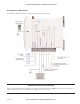
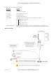
Cooper Bussmann BU-905U-L-T Transmitter Quick Start Guide Unit Components and Connections Your BU-905U-L-T Transmitter unit has the following components and terminal connections: IMPORTANT ELECTRICAL SAFETY INFORMATION In order to comply with Electrical Safety Regulations, this module must be installed in an Electrical AND Fire enclosure. This enclosure may be a single or multiple enclosures. Access to the module is to be made by a Service Person only. 3A1577Rev1.8 www.cooperbussmann.
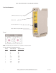
Cooper Bussmann BU-905U-L-T Transmitter Quick Start Guide Front Panel Components SMA Antenna Connector at Top of Unit Indicator LEDs RS232 Configuration Port Rotary Switch for Setpoint Settings The triangle on the rotary switch indicates the current position, for example: NOTE: To avoid damaging the rotary switch, use a screwdriver to change the position. The rotary switch uses the following setpoint levels: 4 Position Lower Level (mA) Upper Level (mA) 1 4.8 6.4 2 6.4 8.0 3 8.0 9.
Cooper Bussmann BU-905U-L-T Transmitter Quick Start Guide The LEDs on the front panel indicate the unit status: LED Status Indicates None No power supply. OK LED Green Current status of the unit OK. OK LED Red Fault condition detected in unit. TX LED Flashes Transmitting Message. PG LED on Configuration Cable Connected. Input LED ON Input LEDs (i.e., D1,D2, SP, AZ.) light when the corresponding input is active. All LEDs medium flash D1 Digital Input 1 is active (Low).
Cooper Bussmann BU-905U-L-T Transmitter Quick Start Guide Resetting Your Unit to Factory Defaults To reset the default factory configuration: 1. Set the RSSI rotary switch to position 0 using a screwdriver. 2. Power on the BU-905U-L-T transmitter. 3. The BU-905U-L-T transmitter flashes all LEDs at medium flash (i.e., 1.6Hz). NOTE: If the LEDs do not flash, you must repeat steps 1 and 2 until the LEDs flash before continuing. 4. Set the RSSI rotary switch to another position (i.e.
Cooper Bussmann BU-905U-L-T Transmitter Quick Start Guide Industry Canada: BU-905U-L Wireless I/O Module RSS-119 - This device has been type accepted for operation by Industry Canada in accordance with RSS-119 of the Industry Canada rules. See the label on the unit for the specific Industry Canada certification number and any other certification designations. NOTE: Any changes or modifications not expressly approved by Cooper Bussmann P/L could void the user’s authority to operate this equipment.
Customer Assistance Customer Satisfaction Team Application Engineering Available to answer questions regarding Cooper Bussmann products & services Monday-Friday, 8:00 a.m. – 4:30 p.m. for all US time zones. Contact: s Toll-free phone: 855-287-7626 (855-BUSSMANN) s Toll-free fax: 800-544-2570 s E-mail: busscustsat@cooperindustries.com Technical assistance is available to all customers. Staffed by degreed engineers, this application support is available Monday-Friday, 8:00 a.m. – 5:00 p.m.