CT02MAN 2002 CABLE TRAY MANUAL Based on the 2002 National Electrical Code®
Table of Contents Page No. Introduction ...................................................................................................................... 2 Why Cable Tray? Safety .................................................................................................................... 3 Dependability ........................................................................................................... 4 Space Savings ......................................................................
INTRODUCTION The B-Line Cable Tray Manual was produced by B-Line's technical staff. B-Line has recognized the need for a complete cable tray reference source for electrical engineers and designers. The following pages address the 2002 National Electric Code® requirements for cable tray systems as well as design solutions from practical experience. The information has been organized for use as a reference guide for both those unfamiliar and those experienced with cable tray.
WHY CABLE TRAY? BECAUSE A CABLE TRAY WIRING SYSTEM PROVIDES SAFE AND DEPENDABLE WAYS TO SAVE NOW AND LATER CABLE TRAY SAFETY FEATURES Large numbers of electrical engineers have limited detail knowledge concerning wiring systems. There is the tendency by engineers to avoid becoming involved in the details of wiring systems, leaving the wiring system selection and design to designers or contractors.
CABLE TRAY DEPENDABILITY CABLE TRAY SPACE SAVINGS A properly designed and installed cable tray system with the appropriate cable types will provide a wiring system of outstanding dependability for the control, communication, data handling, instrumentation, and power systems. The dependability of cable tray wiring systems has been proven by a 40 year track record of excellent performance.
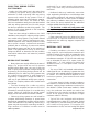
CABLE TRAY WIRING SYSTEM COST SAVINGS monitored. For an equal capacity wiring system, only a few cable tray runs would have to be monitored. Usually, the initial capital cost is the major factor in selecting a project's wiring system when an evaluation is made comparing cable tray wiring systems and conduit wiring systems. Such an evaluation often covers just the conductors, material, and installation labor costs.
COST - Cable Tray vs. Conduit (Equivalent Conductor Fill Areas) 16000 14000 12000 Material Cost Labor Cost @ $25/hr per NECA labor units. 10000 Total Installed Cost ($) 8000 6000 4000 2000 0 Ladder Cable Tray 1 Solid Bottom Cable Tray 2 EMT 3 Rigid Steel Conduit 4 Installation: 200 linear feet of cable supported with four 90° direction changes and all trapeze supports on 8 ft. spans. 1. Hot dip galvanized steel, 18" wide, ladder cable tray (9" rung spacing) with all hardware. 2.
• The higher the elevation of the wiring system, the more important the number of components required to complete the installation. Many additional man-hours will be required just moving the components needed for the conduit system up to the work location. to be made on a weekend or on a holiday at premium labor costs to avoid shutting down production or data processing operations during normal working hours.
IN MOST CASES AN OBJECTIVE EVALUATION OF THE REQUIREMENTS FOR MOST HIGH DENSITY WIRING SYSTEMS WILL SHOW THAT A CABLE TRAY WIRING SYSTEM PROVIDES A WIRING SYSTEM SUPERIOR TO A CONDUIT WIRING SYSTEM. • Moisture is a major cause of electrical equipment and material failures. Breathing due to temperature cycling results in the conduits accumulating relatively large amounts of moisture.
AN IN-DEPTH LOOK AT 2002 NEC® ARTICLE 392 - CABLE TRAY (The following code explanations are to be used with a copy of the 2002 NEC®.) To obtain a copy of the NEC® contact: National Fire Protection Association® 1 Batterymarch Park • P.O. Box 9101 Quincy, Massachusetts 02269-9101 1-800-344-3555 392.1. Scope. overall strength of the cable tray. Specifiers should be aware that some cable tray manufacturers do not account for this load reduction in their published cable tray load charts.
Channel cable tray systems (B-Line's cable channel) are available in 3, 4, and 6 inch widths with ventilated or solid bottoms. The 2002 NEC® now recognizes solid bottom cable channel. Prior to the 2002 Code, the NEC® did not have any specific provisions for the use of solid cable channel.
The words "and other similar structures." were incorporated in Section 392.1 for future types of cable tray that might be developed, such as center supported type cable tray. All the technical infor mation developed by the 1973 N E C ® Technical Subcommittee on Cable Tray for Article 318 - Cable Trays was based on cable trays with side rails and this technical information is still the basis for the 2002 NEC® Article 392 - Cable Trays.
Cable Tray Materials The 2002 NEC® also added a new requirement that where cables in tray are exposed to the direct rays of the sun, they shall be identified as sunlight resistant for all occupancies, not just industrial. Metallic cable trays are readily available in aluminum, pregalvanized steel, hot-dip galvanized after fabrication, and stainless steel. Aluminum cable tray should be used for most installations unless specific corrosion problems prohibit its use.
on the use of Type MI cable is that it may not be used where it is exposed to destructive corrosive conditions unless protected by materials suitable for the conditions. Type MI cable without overall nonmetallic coverings may be installed in ducts or plenums used for environmental air and in other space used for environmental air in accordance with Sections 300.22(B) and (C). Cable tray may be installed as a support for Type MI cable in any location except where the cable is installed in a hoistway.
instrumentation and data handling systems. These are very critical circuits that impact on facility safety and on product quality. Type ITC cable must be supported and secured at intervals not exceeding 6 feet [See Section 727.4].
392.3. Uses Permitted. (B) In Industrial Establishments. (1) Single Conductor. copper EGC should not be used. Under such conditions, electrolytic corrosion of the aluminum may occur. For such installations, it is desirable to use a low cost 600 volt insulated conductor and remove the insulation where connections to equipment or to equipment grounding conductors are made. (See Section 392.7. Grounding, for additional Section 392.3(B)(1) covers 600 volt and Type MV single conductor cables.
This is an extremely important exception stating that cable seals are not required when a cable goes from an unclassified area through a classified area then back to an unclassified area. 501-4(A)(1)(d) allows Type ITC-HL cable to be installed in Class I, Division I areas if they have a gas/vapor tight continuous corrugated aluminum sheath with a suitable plastic jacket over the sheath and provided with termination fittings listed for the application. 501.5. Sealing and Drainage.
Note 1. The cables are limited to a single layer with spacing between cables equal to the diameter of the largest adjacent cable. This means that the cables must be tied down at frequent intervals in horizontal as well as vertical cable trays to maintain the cable spacing. A reasonable distance between ties in the horizontal cable tray would be approximately 6 feet (See Section 392.8 Cable Installation - Tying cables to cable trays). in ordinary locations. 503.3. Wiring Methods.
high amperage short circuit if a low resistance metallic path (metallic cable tray or metallic raceway) is present [See information under Section 392.5(F) Nonmetallic Cable Trays]. not so. Only the appropriate multiconductor cable types as per Section 392.3(A) may be installed in solid bottom cable trays. Cable tray may be used to support data process wiring systems in air handling areas below raised floors as per Sections 300.22(D) and 800.52(D). 392.4. Uses Not Permitted.
for the cable tray is determined by adding all the applicable component loads. The cable load + the concentrated static loads + ice load (if applicable) + snow load (if applicable) + wind load (if applicable) + any other logical special condition loads that might exist. This total load is used in the selection of the cable tray. installed indoors, a load symbol "B" cable tray would be adequate.
392.5. Construction Specifications. (B) Smooth Edges. moisture content, however the minimum density that should be used for snow is 5 pounds per cubic foot. The engineer will have to contact the weather service to determine the potential snow falls for the installation area or consult the local building code for a recommended design load. Usually cable trays are installed within structures such that the structure and equipment shelter the cable trays from the direct impact of high winds.
support. Although the use of cable tray fittings is not mandatory, it is often desirable to use them when possible to improve the appearance of the installation. to insure the longevity of the product. Ambient temperature is also a design consideration when FRP cable tray is used. An ambient temperature of 100°F will decrease the loading capacity of poltester resin fiberglass cable tray by 10%. 392.5. Construction Specifications. (F) Nonmetallic Cable Tray. 392.6. Installation. (A) Complete System.
There are some designers, engineers, and inspectors that do not think that cable tray is a mechanical support system just as strut is a mechanical support system. Cable tray is not a raceway in the NEC® but some designers, engineers, and inspectors attempt to apply the requirements for raceway wiring systems to cable tray wiring systems even when they are not applicable. Cable tray wiring systems have been used by American industry for over 35 years with outstanding safety and continuity of service records.
392.6. Installation. (C) Supports. high winds, the light duty clips are not capable of restraining the covers. Outdoor cover installations should be overlapped at expansion joint locations to eliminate cover buckling. Covers which fly off the cable tray create a serious hazard to personnel, as was the case at a Texas gulf coast chemical plant where operators would not leave their control room because hurricane force winds had stripped many light gauge stainless steel covers off a large cable tray system.
392.6. Installation. (E) Multiconductor Cables Rated 600 Volts or Less. No. 2: Where separated with a fixed solid barrier of a material compatible with the cable tray. Cables containing 300 or 600 volt insulated conductors may be installed intermingled in the same cable tray which is different from the requirements for raceways.
Accessible: (As applied to wiring methods) Capable of being removed or exposed without damaging the building structure or finish, or not permanently closed in by the structure or finish of the building. to be bonded to the cable tray. A fitting may be used for this bonding even though it will not count as a mechanical support. Over 99 percent of the conduits supported on cable trays are the result of conduits being terminated on the cable tray side rails [See Section 392.8(C)].
UL Listed Conduit To Cable Tray Clamp 2 Inch Rigid Metal Conduit Conduit Bushing Cable Tray Side Rail 16 Feet Cable Tray See NEC® Table 344.30(B)(2) To Obtain The Support Requirements For Other Conduit Sizes. Position Of The First Conduit Support From The Cable Tray (Conduit Must Be Securely Fastened To The Support) Conduit Terminated On And Supported By The Cable Tray Side Rail. Installation For Qualifying Industrial Facilities As Per 392.6(J).
Discontinuous Joints Require Bonding For Qualifying Facilities EGCs in the Cables or EGC Cables Are Not Required If Rating Of The Feeder Overcurrent Device Permits Using The Tray For the EGC Bond Conduit Three Phase Motor Installation Motor Control Center Bond Switchgear Transformer (Solidly Grounded Secondary) Bonding Jumper Not Required For Rigidly Bolted Joints EGC In Cable EGC Building Steel Ground Bus Bonded To Enclosure Lightning Protection Grounding System Ground Correct Bonding Practices To
392.7. Grounding. (B) Steel or Aluminum Cable Tray Systems. (1) & (2) The subject of using cable tray for equipment grounding conductors was thoroughly investigated by the 1973 NEC ® Technical Subcommittee on Cable Tray. Many calculations were made and a number of tests were performed by Monsanto Company Engineers at the Bussman High Current Laboratory. The test setup to verify the capability of cable tray to be used as the EGC is shown in Figure 1 on page 29.
Temperature Rise Test Material Thickness: 0.125" Aluminum or 14 Gauge Steel 91/2" 4" Cross Section Area, 2 Rails: Aluminum - 1.00 sq. in. Steel - 0.76 sq. in. 13/16" 41/2" 4" 3/8" 0.
Cable Tray Label Do Not Use As A Walkway, Ladder, Or Support For Personnel. Use Only As A Mechanical Support For Cables, Tubing and Raceways. Catalog Number: 24A09-12-144 STR SECTION 1 of 1 (and description) Shipping Ticket: Mark Number: Purchase Order: Minimum Area: Load Class: 260203 00 001 78101115400 D798981 1.000 SQ. IN.
392.8. Cable installation. (C) Bushed Conduit and Tubing. Where run in separate raceways or cables, the raceways or cables shall have the same physical characteristics. Conductors of one phase, neutral, or grounded circuit shall not be required to have the same physical characteristics as those of another phase, neutral, or grounded circuit conductor to achieve balance. For most installations, using a conduit to cable tray clamp for terminating conduit on cable tray is the best method.
Compatibility Of Cable Tray Types And Cable Trays Based On The NEC® problems due to operating standard three conductor cables with standard sized EGCs in parallel. This has been a standard industrial practice for over 40 years with large numbers of such installations in service. This change was made without any safety or technical facts to justify this change. 3", 4", & 6" Wide Solid or Ventilated Channel Cable Tray Solid Bottom Cable Tray Ventilated Trough Cable Tray To comply with Section 250.
392.9. Number of Multiconductor Cables. Rated 2000 Volts or less, in Cable Trays. (B) Multiconductor Control and/or Signal Cables Only. side rail (Example: 3 inches x 6 inches inside cable tray width x 0.389 = 7.0 square inch fill area. This is the first value in Column 1 of Table 392.9. All succeeding values for larger cable tray widths are identically calculated).
392.9. Number of Multiconductor Cables, Rated 2000 Volts, Nominal, or Less, in Cable Trays. (C) Solid Bottom Cable Trays Containing Any Mixture. (2) Cables Smaller Than 4/0 tray width for the type of cable covered in this section is similar to that shown on Appendix Sheet 6 page 50. [Example 392.9(B)] 392.9. Number of Multiconductor Cables, Rated 2000 Volts, Nominal, or Less in Cable Trays. (E) Ventilated Channel Cable Trays.
392.9(F)(2) Cable Tray Width The fill areas for combinations of multiconductor cables of any type installed in solid channel cable tray. Solid Channel Cable Tray Size Maximum Allowable Fill Area 2 Inch Wide 0.8 Square Inches 3 Inch Wide 1.1 Square Inches 4 Inch Wide 2.1 Square Inches 6 Inch Wide 3.2 Square Inches Single Conductor Size Dia. In. (Note) #1 Area Sq. In. 6 In. 9 In. 12 In. 18 In. 24 In. 30 In. (Note #2) 36 42 In. In. 1/0 0.58 -- 10 15 20 31 41 51 62 72 2/0 0.
392.10. Number of Single Conductor Cables, Rated 2000 Volts or Less in Cable Trays. (B) Ventilated Channel Cable Trays. 392.9. The ampacities in Table 310.16 are based on an ambient temperature of 30˚ Celsius. Conduit and cable tray wiring systems are often installed in areas where they will be exposed to high ambient temperatures.
2.11. Ampacity of Cables Rated 2000 Volts or Less in Cable Trays. (B) Single Conductor Cables. Single conductor cables can be installed in a cable tray cabled together (triplexed, quadruplexed, etc.) if desired. Where the cables are installed according to the requirements of Section 392.10, the ampacity requirements are shown in the following chart as per Section 392.11(B)(1), (2), (3), & (4): Sec. No. Cable Sizes (1) 600 kcmil and Larger No Cover Allowed (**) 310.17 and 310.19 0.
Provision No. 2: Where multiconductor cables are installed in a single layer in uncovered cable trays with a maintained spacing of not less than one cable diameter between cables, the ampacity shall not exceed the allowable ampacities of Table 310.71 and 310.72. If the cable tray does not have covers and the conductors are installed in a single layer spaced not less than one cable diameter apart, the cable conductor ampacities can be 100 percent of the ambient temperature corrected capacities in Tables 310.
• Cable Tray Tag Numbers - The tagging system should be developed by the design personnel with identification numbers assigned to cable tray runs on the layout drawings. Cable tray tag numbers are used for controlling the installation of the proper cable tray in the correct location, routing cables through the tray system and controlling the cable fill area requirements. no cable pulling equipment is required.
CABLE TRAY ACCESSORIES. CABLE TRAY MAINTENANCE AND REPAIR B-Line manufactures a full line of prefabricated accessories for all types of B-Line cable trays. The use of the appropriate accessories will provide installation cost and time savings. In addition to providing desirable electrical and mechanical features for the cable tray system, the use of the appropriate accessories improves the physical appearance of the cable tray system. Some of the most common accessories are shown below.
CABLE TRAY. THERMAL CONTRACTION AND EXPANSION NEC® Section 300.7(B) states that 'Raceways shall be provided with expansion joints where necessary to compensate for thermal expansion or contraction.' NEC® Section 392 does not address thermal contraction and expansion of cable tray. One document which addresses expansion is the NEMA Standards Publication No. VE 2, Section 4.3.2.
Max. Temp. C° 50 Metal Temperature At Time Of Installation (F° or C°) 40 Min. Temp. F° F° 130 130 110 110 1 90 90 20 70 70 10 50 50 0 30 -10 10 10 -20 -10 -10 30 -30 this intersection point, project down to the gap setting horizontal axis to find the correct gap setting value (Example's Value: 3/8 inch gap setting). This is the length of the gap to be set between the cable tray sections at the expansion joint. The plotted High - Low Temperature Range in Figure 4-13B is 128° F.
Cable Tray Manual Cooper B-Line, Inc 43
Appendix Pages Appendix Sheet 1 ........................................................................................................ 45 Temperature Rise Tests, Cable Tray Connectors, Class II Aluminum & Steel Ladder Tray Appendix Sheet 2 ........................................................................................................ 46 Temperature Rise Tests, Conduit Clamps For Bonding Rigid Conduit To Cable Tray Appendix Sheet 3 ..................................................................
TABLE I TEMPERATURE RISE TESTS, CABLE TRAY CONNECTORS, CLASS II ALUMINUM LADDER CABLE TRAY Test Current Amps And Fuse Size* I2T Test Time Cycles mult. by 106 Connector Data C2 C1 C3 Type No. & Temp. Type Of Type Rise Of Connector Bolts °C Connector No. & Type Bolts Temp. Rise °C Type Of Connector 7,900 1,200A Fuse 66 69 Adj. Vert.
Conduit Conduit Cable Tray Right Angle Beam Clamp To Current Source To Current Source UL Listed Conduit Clamp (9ZN-1158) Cable Tray Test Set-Up Conduit Clamp Detail CIRCUIT ARRANGEMENT FOR RIGID CONDUIT TEMPERATURE RISE TESTS TABLE III TEMPERATURE RISE TESTS, CONDUIT CLAMPS FOR BONDING RIGID CONDUIT TO CABLE TRAY Test Current Amperes Test Time Cycles I2T mult. 106 Size Material Class 36,000 16 344.7 4" Aluminum 20,900 60.5 441.2 4" 12,100 178 433.
Example - NEC® Section 392.9(A)(1) Width selection for cable tray containing 600 volt multiconductor cables, sizes #4/0 AWG and larger only. Cable installation is limited to a single layer. The sum of the cable diameters (Sd) must be equal to or less than the usable cable tray width. 30" Usable Cable Tray Width 29.
Example - NEC® Section 392.9(A)(2) Width selection for cable tray containing 600 volt multiconductor cables, sizes #3/0 AWG and smaller. Cable tray allowable fill areas are listed in Column 1 of Table 392.9. 30" Usable Cable Tray Width Cross Section Of The Cables And The Cable Tray Cable tray width is obtained as follows: Item Number List Cable Sizes (A) List Cable Cross Sectional Areas (N) List Number of Cables 1. 2. 3. 4. 3/C #12 AWG 4/C #12 AWG 3/C #6 AWG 3/C #2 AWG 0.17 sq. in. 0.19 sq. in. 0.
Example - NEC® Section 392.9(A)(3) Width selection for cable tray containing 600 volt multiconductor cables, sizes #4/0 AWG and larger (single layer required) and #3/0 AWG and smaller. These two groups of cables must have dedicated areas in the cable tray. 24" Usable Cable Tray Width 9.09" 1.93" 12.
Example - NEC® Section 392.9(B) Cable Tray containing Type ITC or Type PLTC Cables 6" Usable Cable Tray Width 4" Usable Cable Tray Depth Cross Section Of The Cables And The Cable Tray 50% of the cable tray useable cross sectional area can contain type PLTC cables 4 inches x 6 inches x .050 = 12 square inches allowable fill area. 2/C - #16 AWG 300 volt shielded instrumentation cable O.D. = 0.224 inches. Cross Sectional Area = 0.04 square inches. 12 sq. in.
Table 250.122. Minimum Size Equipment Grounding Conductors for Grounding Raceways and Equipment Rating or Setting of Automatic Overcurrent Device in Circuit Ahead of Equipment, Conduit, etc.
CABLE TRAY SIZING FLOWCHART Start Here Sizing Cable Tray Per NEC 392 392.12 W ≥ Sd (single layer) No 2000V or less cables Yes No Solid Bottom Tray Yes Vented Channel Tray Ladder or Vented Trough Tray No Yes 392.10 Not recognized by ® the NEC 392.10(B) W ≥ Sd Yes 392.10(A)(1) W ≥ Sd Yes S/C 1000 kcmil or larger Yes S/C 1/0 or larger No Multiconductor cables Yes Continued on next page No 392.3(B)(1)(a) Not permitted ® by the NEC No 392.10(A)(2) W ≥ A/1.
CABLE TRAY SIZING FLOWCHART Ampacity: See pages 36 - 38 for information on cable ampacity that might affect the cable tray sizing flowchart. See pages 15 - 17 for information on hazardous (classified) areas that might affect the cable tray sizing flowchart. Yes Ladder or Vented Trough Tray No Yes M/C 4/0 or larger Yes Yes 392.9(A)(1) W ≥ Sd (single layer) No M/C smaller than 4/0 No Solid Bottom Tray M/C 4/0 or larger 392.9(A)(2) W ≥ A/1.
CABLE TRAY INSTALLATION & SPECIFICATION CHECKLIST Project Information Project Name: Location: Contractor/Engineer: Phone: # Project Information Distributor Name: Location: Contact: Phone: Fax: Cable Tray NEMA Load Depth* Material Aluminum Pre-Galvanized Steel Hot-Dip Galvanized Steel 304 Stainless Steel 316 Stainless Steel Fiberglass-Polyester Resin Fiberglass-Vinyl Ester Resin Width 6” 9” 12” 18” 24” 30” 36” 42” ❏ ❏ ❏ ❏ ❏ ❏ ❏ ❏ ❏ ❏ ❏ ❏ ❏ ❏ ❏ 2” ** 3” 4” 5” 6” * Load depth is 1” less than siderail
CABLE TRAY INSTALLATION & SPECIFICATION CHECKLIST Cable Channel Width Material ❏ ❏ ❏ ❏ ❏ ❏ ❏ Aluminum Pre-Galvanized Steel Hot-Dip Galvanized Steel 304 Stainless Steel 316 Stainless Steel Fiberglass-Polyester Resin Fiberglass-Vinyl Ester Resin * Fiberglass only.
Footnotes: 1 NEMA Standard VE-2, Section 4, Installation 4.3 Straight Section Installation - 4.3.1. Horizontal Cable Tray Straight Sections states that straight section lengths should be equal to or greater than the span length to ensure not more than one splice between supports. Additional Cable Tray Resources Cable Tray Institute 1300 N. 17th Street Rosslyn, VA 22209 National Electrical Manufacturers Association 1300 N. 17th Street Rosslyn, VA 22209 www.cabletrays.com www.nema.
B-Line Wire Management Resources B-Line Product Catalogs • Cable Tray Systems (CT-02) . . . . . . . . . . . . . . . . . . . . . . . . . . . . . Metallic, Two Siderail System Commercial and Industrial Applications • Fiberglass Cable Tray (CT01FRP) . . . . . . . . . . . . . . . . . . . . . . . . Non-Metallic, Two Siderail Trays Non-Metallic Strut Systems • Cent-R-Rail® (CR-02) . . . . . . . . . . . . . . . . . . . . . . . . . . . . . . . . . . . .
Ask the Experts Cent-R-Rail Redi-Rail Non-Metalic Cable Tray Wire Basket Metalic Cable Tray Cooper B-Line, Inc 509 W.