
Installation Manual

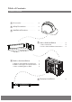
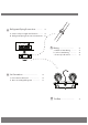
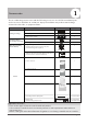

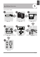


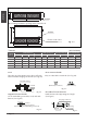

Fig. 4.3
Air lter
Descending ventilation opening and mounted hook
Air lter
Electric control box
Table.4-1 (unit: inch/mm)
MODEL
(Btu/h)
Outline dimension
A B C
air outlet opening size
D E F
air return opening size
Size of mounted lug
I
J
G
H
18K
24K
30K~36K
36K~60K
9K/12K
7.9/200 19.9/50627.6/700
6/152 21.1/53717.7/450 7.3/186 29.2/74123.6/599
14.2/360
Indoor Unit
Installation
Fig. 4.6
Fig. 4.7
Original concrete bricks
Use an embedding screw bolt, crock, and stick
harness.(See Fig.4.6)
Steel Roof beam structure
Install and use the supporting steel angle.
(See Fig.4.7)
Fig. 4.4
Wood
Place the wood mounting across the roof beam,
then install the hanging screw bolts.(See Fig.4.4)
Wood mounting
Roof beam
Hanging screw bolts
Ceiling
Fig. 4.5
New concrete bricks
Inlay or embed the screw bolts. (See Fig. 4.5)
(Blade shape insertion)
(Slide insertion)
Steel bar
Embedding screw bolt
(Pipe hanging and embedding screw bolt)
Hanging screw bolt
Hanging
bolts
Supporting
steel angle
Page 10
Air inlet dimensions
9.8/249 30.5/77453.5/1360
11.8/300 34.4/87447.2/1200
6.9/175 46.7/118627.6/700
8.9/227 41.1/104431.5/800
8.9/228
11/280
55.1/140049.6/1261
48.8/124043.3/1101
23.5
/
598
27.4
/
697
9.8/249 30.5/77443.3/1100 6.9/175 36.5/92627.6/700
8.9/228
44.9/114039.4/1001
23.5
/
598
8.3/210 26.5/67434.6/880 5.4/136 27.8/70623.6/600
7.5/190
36.2/92030.8/782
20
/
508