
Installation Manual

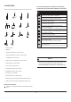
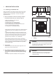
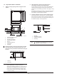
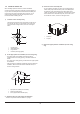
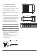
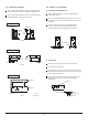
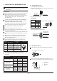
Table Of Contents

3 INSTALLING THE REFRIGERANT PIPE
Execute heat insulation work completely on both sides of the gas
piping and liquid piping. Otherwise, water leakage may result.
(When using a heat pump, the temperature of the gas piping can
reach approximately 120
O
C/248
O
F. Use insulation that is
sufficiently resistant.)
All field piping must be provided by a licensed refrigeration
technician and must comply with the relevant local and
national codes.
Coat the flare both inside and outside with ether oil or ester oil.
9
Coat here with ether oil or ester oil
Precautions
3.1 Flaring the pipe end
1) Cut the pipe end with a pipe cutter.
2) Remove burrs with the cut surface facing downward so that the
chips do not enter the pipe.
5) Ensure that the flaring is made properly.
Before rigging tubes, check which type of refrigerant is used.
Use a pipe cutter and flare suitable for the refrigerant.
Only use annealed material for flare connections.
Do not mix anything other than the specified refrigerant, such as
air, inside the refrigerant circuit.
If refrigerant gas leaks while you are working, ventilate the area.
Toxic gas may be emitted when the refrigerant gas is exposed to a
fire.
Make sure there is no refrigerant gas leak. Toxic gas may be
released when the refrigerant gas is exposed to flames from an
area heater, cooking stove, etc.
Refer to the table below for the dimensions of flare nut spaces
and the appropriate tightening torque. (Over-tightening may
damage the flare and cause leaks.)
Pipe gauge
(mm)
Outer diam.
(mm)
Tightening torque
A (mm)
Max.
1.3
1.6
1.8
2.2
Min.
0.7
1.0
1.0
2.0
Flare dimension
A (mm)
Flare shape
O 6.35 (1/4 in)
O 6.35 (1/4 in)
15-16 N. m
(153-163 kgf. cm)
8.3-8.7
0.327-0.343 in
12.0-12.4
0.472-0.488 in
15.4-15.8
0.606-0.622 in
18.6-19.0
0.732-0.748 in
25-26 N. m
(255-265 kgf. cm)
35-36 N. m
(357-367 kgf. cm)
45-47 N. m
(459-480 kgf. cm)
O 9.52 (3/8 in)
O 9.52 (3/8 in)
O 12.7 (1/2 in)
O 12.7 (1/2 in)
O 15.9 (5/8 in)
O 15.9 (5/8 in)
R0.4-0.8
45
2
90
4
A
o
o
1 Torque wrench
2 Flare nut
3 Piping union
4 Spanner
1 2
3
4
Align the centers of both flares and tighten the flare nuts 3 or 4
turns by hand. Then tighten them fully with the torque wrenches.
3.2 Refrigerant piping
Ensure that the height drop between the indoor and outdoor units
and the length of the refrigerant pipe meet the following
requirements:
Capacity
(Btu/h)
Types of models
Max. allowable
piping length
15 m (49.2 ft)
25 m (82 ft)
25 m (82 ft)
25 m (82 ft)
9K - 12K
9K - 12K
9K - 12K
9K - 12K
T1 condition
Split-type air conditioner
R410A inverter
Split-type air conditioner
T3 condition
(outdoor unit down)
T3 condition
(outdoor unit up)
Max. allowable
piping height
8 m (26.2 ft)
10 m (32.8 ft)
10 m (32.8 ft)
15 m (49.2 ft)
25 m (82 ft)
30 m (98.4 ft)
30 m (98.4 ft)
30 m (98.4 ft)
18K
18K
18K
18K
15 m (49.2 ft)
20 m (65.6 ft)
15 m (49.2 ft)
20 m (65.6 ft)
Cut exactly at
right angles
Remove burrs
must be flaw-free.
The flare's inner surface
The pipe end must
be evenly flared in a
perfect circle.
Make sure that the
flare nut is fitted.
Die
Copper pipe
A
Set exactly at the position shown below.
3) Put the flare nut on the pipe.
4) Flare the pipe.
(in = 25.4 mm)
0.016-0.031 in
In cases where the temperature and humidity of the refrigerant
piping sections might exceed 30
O
C/86
O
F or Rh 80%, reinforce
the refrigerant insulation (0.8in (20 mm) or thicker).
Condensation may form on the surface of the insulating material.