
Installation Manual
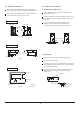
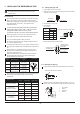


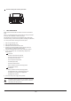

Table Of Contents

11
1 Liquid pipe
2 Gas pipe
3 Insulation for liquid pipe fitting
4 Insulation for gas pipe fitting
5 Clamps
(use 2 clamps per insulation)
6 Indoor unit
Be sure to insulate local piping all the way into the
pipe connections inside the unit. Exposed piping may
facilitate condensation or may cause burns when
touched.
Make sure that no oil remains on the plastic parts of
the decoration panel (optional equipment). Oil may
damage and cause degradation to plastic parts.
3) Insulate as shown in the figure below
1
2
3
4
5
6
A
B
C
Piping insulation material (field supply)
Flare nut connection
Insulation for fitting (field supply)
Piping insulation material (main unit)
Indoor unit
Clamp (field supply)
Turn seams up
Attach to the base
Tighten the part other than the piping insulation material
Piping insulation procedure
Gas piping Liquid piping
1
3
5
2
4
1
1
6
6
6
6
4
4
5
5
3
3
2
2
A
A
C
C
B
B
3.5 Additional refrigerant charge
CAUTION
Refrigerant should only be charged after the leak test and
vacuum pumping are performed.
Check the type of refrigerant to be used on the machine
nameplate. Charging with an unsuitable refrigerant may
cause explosions and accidents, so always ensure that the
appropriate refrigerant is charged.
Refrigerant containers must be opened slowly.
The outdoor unit is factory charged with refrigerant. Calculate
the added refrigerant necessary according to the diameter and
length of the liquid pipe of the outdoor/indoor unit connection.
3.6 Refrigerant piping work
1) Caution on pipe handling
Protect the open end of the pipe against dust and moisture.
All pipe bends should be done as gently as possible with a
pipe bender.
2) Be sure to insulate both the gas and liquid piping. Use
separate thermal insulation for each. See the figure
below.
Be sure to add the proper amount of additional refrigerant.
Failure to do so may result in reduced performance.
Pipe length
Up to 15 m (49.2 ft) More than 15 m (49.2 ft)
Not less than 15 min
Not less than 10 min
Run time
*2. If the compound pressure gauge pointer swings back,
the refrigerant may contain water content or a pipe joint may be
loose. Check all pipe joints and retighten nuts as needed, then
repeat steps 2 through 4.
Be sure to
use a cap.
If no flare cap is
available, cover the
flare mouth with
tape to keep dirt and
water out.
Inter-unit wire
Liquid pipe
Liquid pipe
insulation
Drain hose
Finishing tape
Gas pipe
insulation
Gas pipe
Wall
Rain
6
Pipe length and refrigerant amount:
Connective
pipe length
Less
than 7.5 m
More
than 7.5 m
Air purging
method
Use a vacuum
pump
.
Use a vacuum
pump
Additional amount of refrigerant to be charged
Liquid side: 6.35 mm (1/4 in)
R410A: (Pipe length: 7.5(25))x15g/m(0.16oz/ft)
Liquid side: 9.52 mm (3/8 in)
R410A: (Pipe length: 7.5(25))x30g/m(0.32oz/ft)