
User Manual
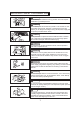
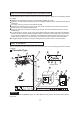
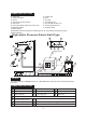
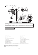
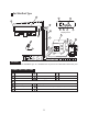
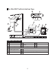
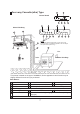
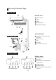
Table Of Contents

This picture is based on the type of 18000Btu/h, So the appearance and function may be
slightly different from the unit you purchased.
12 13
14
15
2
6
7
4
3
8
5
1
9
11
10
Indoor Unit Assy
Outdoor Unit Assy
Control board
Inlet
Outlet
Manual
OPERATION
TIMER
DEF./FAN.
ALARM
12
12
13
13
14
14
15
15
11
11
10
10
10
SET
OPERATION
TIMER
DEF./FAN.
ALARM
Indoor Unit
Air outlet
Drain hose
Drain Pump (Internal installed),water drain from indoor unit.
Infrared Signal receiver
Timer indicator
Alarm indicator
Defrost indicator heating/cooling type or fan indicator (cooling
only type)
Outdoor Unit
Vertical louver
Manual button/SET button
Remote Controller
Connecting pipe
Run lamp
1
7
10
4
9
13
15
2
3
Parts Names:
11 12
14
8
5
6
Air Inlet (Air filter installed inside to prevent the dust)
Four-way Cassette(slim) Type
7
NOTE:
These three indication lamps flash in cycles when solar
PV ECO function is activated.(Applicable to the unit adopts
solar photovoltaic system only.)