SOPHIA MULTI-ZONE DUCTLESS INVERTER SPLIT AIR CONDITIONER WITH HEAT PUMP CASSETTE TYPE INSTALLATION MANUAL INDOOR UNIT Models: CH-09MSPHCT-230VI CH-12MSPHCT-230VI CH-18MSPHCT-230VI CH-24MSPHCT-230VI IMPORTANT NOTE: • Read this manual carefully before installing or operating your new air conditioning unit. Make sure to save this manual for future reference. • This manual only describes the installation of outdoor unit. When installing the indoor unit, refer to the installation manual of indoor unit.
CONTENTS Install strictly according to these installation instructions. If installation is defective, water leakage, electrical shock, and fire will result. Page PRECAUTIONS ...................................................................................1 INSTALLATION INFORMATION ..........................................................
When there are inflammable materials or gas nearby If the refrigerant leaks during installation, ventilate the area immediately. Toxic gas may be produced if the refrigerant comes into contact with fire. When acid or alkaline liquid is evaporating When other special conditions exist The temperature of the refrigerant circuit will be high, so keep the interconnection cable away from the copper tube. The appliance must be installed in accordance with national wiring regulations.
ACCESSORIES For the following items, take special care during construction and check after installation is finished. Ensure that the following accessories are included with your unit: 2 1 1x 3 1x 2x Mark√ when finished 4 2x Is the indoor unit fixed firmly? The unit may drop, vibrate, or make noise. Is the gas leak test finished? It may result in insufficient cooling or heating. 7 6 5 1x 1x+1x 1x Is the unit fully insulated? Condensate water may drip.
When the conditions in the ceiling exceed 300 C/860 F and a relative humidity of 80%, or when fresh air is inducted into the ceiling, an additional insulation is required (min. 10 mm/0.4 in thickness, polyethylene foam). 1000/39.4 in - 1000/39.4 in Optimum air distribution can be ensured. Nothing blocks air passage. Condensate water can be properly drained. The false ceiling is not on a noticeable incline. There is sufficient clearance for maintenance and service.
1.2 1 2 Where applicable, create the ceiling opening that is necessary for installation (for existing ceilings) - From the side of the opening to the casing outlet, implement the refrigerant and drain piping and wiring for the remote control (unnecessary for the wireless type). Refer to each piping or wiring section. - After making an opening in the ceiling, you may need to reinforce the ceiling beams to maintain the ceiling level and to prevent it from vibrating. Consult the builder for details.
1.3 4) Check if the unit is horizontally level Install the indoor unit - Do not install the unit tilted. The indoor unit is equipped with a built-in drain pump and float switch. (If the unit is tilted against the direction of the condensate flow (the drain piping side is raised), the float switch may malfunction and cause water to drip. - With a water level or water-filled vinyl tube, check if the unit is level at all four corners, as shown in the figure below.
OUTDOOR UNIT INSTALLATION 2.1 Precautions for selecting the location 1) Choose a place solid enough to bear the weight and vibration of the unit, where operation noise will not be amplified. 2) Choose a location where the hot air discharged from the unit or the operation noise will not be a nuisance to neighbors. 3) To lessen the irritation of the operation noise, avoid placing the unit near bedrooms and the like. 4) There must be sufficient space for carrying the unit into and out of the site.
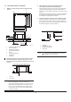
2.4 Outdoor unit installation 2.3 Installation guidelines When a wall or other obstacle is in the path of the outdoor unit inlet or outlet airflow, follow the installation guidelines below. 1) Installing the outdoor unit When installing the outdoor unit, refer to "Precautions for selecting the location." For any of the below installation patterns, the wall height on the outlet side should be 1200 mm (47.2 in) or less.
3 INSTALLING THE REFRIGERANT PIPE 3.1 Flaring the pipe end 1) Cut the pipe end with a pipe cutter. All field piping must be provided by a licensed refrigeration technician and must comply with the relevant local and national codes. 2) Remove burrs with the cut surface facing downward so that the chips do not enter the pipe. Precautions Cut exactly at right angles Execute heat insulation work completely on both sides of the gas piping and liquid piping. Otherwise, water leakage may result.
3.4 Purging air and checking gas leakage 3.3 Installation of the throttle (for some models) ≥5 /19 00mm When piping work is completed, purge the air and check for gas leakage. .7in WARNING Do not mix any substance other than the specified refrigerant into the refrigeration cycle. When refrigerant gas leaks, ventilate the room as soon as possible. The specified refrigerant should always be recovered and should never be released directly into the environment.
Pipe length Up to 15 m (49.2 ft) More than 15 m (49.2 ft) Run time Not less than 10 min Not less than 15 min 2) Be sure to insulate both the gas and liquid piping. Use separate thermal insulation for each. See the figure below. *2. If the compound pressure gauge pointer swings back, the refrigerant may contain water content or a pipe joint may be loose. Check all pipe joints and retighten nuts as needed, then repeat steps 2 through 4. Inter-unit wire Gas pipe 3.
4 CONNECTING THE DRAIN PIPE 4.3 How to perform piping 4.1 Installation of drain piping 1 5 3 6 5 1 4 ≤750/29.5in 2 220/8.7in ≤530/20.9in 1-1.5 m 3-5 ft ≤300/11.8in 0~75 0~3 in Install the drain piping as shown in the figure below and take measures against condensation. Improperly rigged piping could lead to leaks and, eventually, wet furniture and belongings. 1-1.
4.4 Testing of drain piping 5 After the piping work is finished, check if drainage flows smoothy. General instructions Gradually add approximately 1 L of water through the air discharge outlet. See the figure below for how to add water. All field wiring and components must be installed by a licensed electrician and must comply with relevant European and national regulations. 106/4.2 in 65/2.6 in ≥100/3.9in Use copper wire only.
How to connect wiring Remove the control box lid of the indoor unit. Remove the cover of the outdoor unit. Follow the "Wiring diagram label" attached to the indoor unit's control box lid to wire the outdoor unit, indoor unit, and remote control. Securely fix the wires with a field-supplied clamp. Attach the cover of the outdoor unit.
6 INSTALLATION OF THE DECORATION PANEL - After installing the decoration panel, ensure that there is no space between the unit body and the decoration panel. If there is, air may leak through the gap and cause dewdrop. (See the figure below.) Detach the intake grille - Slide the 2 grille hooks toward the middle of the decoration panel. 1 × √ 2 Mount the intake grille 1 2 Intake grille Grille hook Ensure that the buckles at the back of the grille are properly seated in the groove of the panel.
Close the intake grille and the 2 grille hooks 7 TEST OPERATION Make sure the control box lids are closed on the indoor and outdoor units. Refer to ''For the following items, take special care during construction and check after installation is finished'' on page 3. After finishing the construction of the refrigerant piping, drain piping, and electric wiring, conduct the test operation accordingly to protect the unit. Test operation after installing the decoration panel. 1 Open the gas side stop valve.
The design and specifications are subject to change without prior notice for product improvement. Consult with the sales agency or manufacturer for details.