SOPHIA MULTI-ZONE DUCTLESS INVERTER SPLIT AIR CONDITIONER WITH HEAT PUMP UNIVERSAL FLOOR/CEILING INSTALLATION MANUAL INDOOR UNIT Models: CH-18MSPHFC-230VI CH-24MSPHFC-230VI IMPORTANT NOTE: • Read this manual carefully before installing or operating your new air conditioning unit. Make sure to save this manual for future reference. • This manual only describes the installation of outdoor unit. When installing the indoor unit, refer to the installation manual of indoor unit.
CONTENTS PAGE PRECAUTIONS........................................................................................1 INSTALLATION INFORMATION. ..............................................................2 ATTACHED FITTINGS..............................................................................3 INSPECTING AND HANDLING THE UNIT.................................................4 INDOOR UNIT INSTALLATION. ...............................................................4 OUTDOOR UNIT INSTALLATION..........
The appliance must be installed in accordance with national wiring regulations. If the refrigerant leaks during installation, ventilate the area immediately. Toxic gas may be produced if the refrigerant comes into contact with a source of fire. Do not operate your air conditioner in a wet room, such as a bathroom or laundry room. The temperature of the refrigerant circuit will be high, so keep the interconnection cable away from the copper tube.
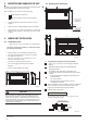
3. ATTACHED FITTINGS Ensure that the following fittings are of full scope. If there are spare fittings, restore them carefully. NAME Remote control and its holder QUANTITY 1. Remote control (on some models) 1 2. Remote control holder (on some models) 1 3. Mounting screw (ST2.9×10-C-H) 2 4. Alkaline dry batteries (AM4) 2 5. User's manual Others SHAPE 6. Installation manual 7.
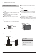
4. INSPECTING AND HANDLING THE UNIT 5.2 Installing the main body At delivery, the package should be checked and any damage should be reported immediately to the the service agent. When handling the unit, take into account the following: B Fragile, handle the unit with care. 1 Keep the unit upright in order to avoid compressor damage. D. Connecting point of refrigerant pipe (gas side) Choose beforehand the path along which the unit will be brought in.
2. Ceiling Installation 20mm NEW CONCRETE BRICKS Inlaying or embedding the screw bolts. (Blade shape insertion) (Slide insertion) Fig. 5-4 Steel bar Fig. 5-10 Embedding screw bolt (Pipe hanging and embedding screw bolt) Fig. 5-5 D. Connecting point of refrigerant pipe (gas side) FOR ORIGINAL CONCRETE BRICKS E. Connecting point of refrigerant pipe (liquid side) Install the hanging hook with an expansible bolt into the concrete 45-50 mm deep to prevent the hook from coming loose. Fig.
6. OUTDOOR UNIT INSTALLATION Outdoor Unit Installation Instructions Step 1: Select installation location The outdoor unit should be installed in the location that meets the following requirements: Place the outdoor unit as close to the indoor unit as possible. Ensure that there is enough room for installation and maintenance. The air inlet and outlet must not be obstructed or exposed to strong wind.
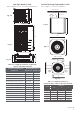
Split Type Outdoor Unit Vertical Discharge Type Outdoor Unit (Refer to 'JHVSFT 6.4, 6.5, 6.6, BOE 6.10 and Table 6.1) (Refer to 'JHVSFT 6.7, 6.8, BOE 6.9 and Table 6.2 (Wall or obstacle) Air Putlet H > 120 cm/47 JO Fig. 6.4 W W Fig. 6.7 H W H Fig. 6.5 D Fig. 6.8 A D (Wall or obstacle) B Fig. 6.6 >30 cm/11.8 JO Table 6.1: Length Specifications of Split Type Outdoor Unit (unit: mm/inch) Outdoor Unit Dimensions Air inlet >30cm/11.8 JO Mounting Dimensions >30cm/11.
60 cm / 23.6” above NOTE: The minimum distance between the outdoor unit and UIF walls described in the installation guide does not apply to airtight rooms. Be suSe to keep the unit unobstructed in at least two of the three directions (M, N, P) (See Fig. 6.10 ) 30 cm Notes Pn Drilling B Hole Jn UIF Wall You must drill a hole in the wall for the refrigerant piping and the signal cable that will connect the indoor and outdoor units.
8. INSTALL THE CONNECTING PIPE Safety Precautions Table 8.1: The Maximum Length Bnd Drop Height Based on Models (Vnit: m/ft.) Type of model WARNING U U U U All field piping must be completed by a licensed technician and must comply with local and national regulations. When the air conditioner is installed in a small room, measures must be taken to prevent the refrigerant concentration in the room from exceeding the safety limit in the event of refrigerant leakage.
Refrigerant Piping Connection Instructions CAUTION U The branching pipe must be installed horizontally. An angle of more than 10° may cause malfunction. U DO NOT install the connecting pipe until both UIF indoor and outdoor units have been installed. U Insulate both the gas and liquid piping to prevent water leakage. Step 2: Remove burrs Burrs can affect the airtight seal of UIF refrigerant piping connection BOE must be completely removed. 1.
Place UIF flaring tool on the form. Turn the handle of the flaring tool clockwise until the pipe is fully flared. Flare the pipe in accordance with the dimensions shown in 5able 8-2. Table 8.2: PIPING EXTENSION BEYOND FLARE FORM Pipe gauge Tightening torque Flare dimension (A) (Unit: mm/Jn ) Min. Max. Ø 6.4 14.2-17.2 N.m (144-176 kgf.cm) 8.3/0.3 8.3/0.3 Ø 9.5 32.7-39.9 N.m (333-407 kgf.cm) 12.4/0.48 12.4/0.48 Ø 12.7 49.5-60.3 N.m (504-616 kgf.cm) 15.4/0.6 15.8/0.6 Ø 15.9 61.8-75.4 N.
9. AIR EVACUATION Flare nut Safety Precautions CAUTION Cap U Use a vacuum pump with a gauge reading lower than -0.1MPa and an air discharge capacity above 40L/min. U The outdoor unit does not need vacuuming. DO NOT open the outdoor unit’s gas and liquid stop valves. U Ensure that the Dompound Neter reads -0.1MPa or below after 2 hours PG PQFSBUJPO. If after hours the gauge reading is still above 0.1MPa, check if there is a gas leak or water inside the pipe.
10. WIRING Connect the connective cables to the terminals as identified by their respective numbers on the terminal block of the indoor and outdoor units. The appliance must be installed in accordance with national wiring regulations. Reinstall the cover or the protection board. The air conditioner should use a separate power supply with rated voltage. 10.
The Specification of Power (Indoor Power Supply) Table 10-1 18 24 30-36 42-48 60 PHASE 1Phase 1Phase 1Phase 1Phase 1Phase FREQUENCY AND VOLT 208-240 V 208-2 40 V 208-2 40 V 208-2 40 V 208-2 40 V 20/16 40/25 50/30 60/45 60/50 MODEL POWER CIRCUIT BREAKER/FUSE (A) Table 10-2 MODEL POWER 30-36 42-60 30-36 42-60 PHASE 3Pha se 3Phase 3Phase 3Phase FREQUENCY AND VOLT 380-420 V 380-420 V 208-2 40 V 208-2 40 V 25/20 25/20 40/25 45/35 CIRCUIT BREAKER/FUSE (A) The Specifica
The Specification of Power (Independent Power Supply) Table 10-5 MODEL 18 24 30-36 42-48 60 PHASE POWER (indoor) FREQUENCY AND VOLT 1Phase 1Phase 1Phase 1Phase 1Phase 208-240 V 208-2 40 V 208-2 40 V 208-2 40 V 208-2 40 V CIRCUIT BREAKER/FUSE (A) 20/16 20/16 20/16 20/16 20/16 PHASE POWER (outdoor) FREQUENCY AND VOLT 1Phase 1Phase 1Phase 1Phase 1Phase 208-240 V 208-2 40 V 208-2 40 V 208-2 40 V 208-2 40 V CIRCUIT BREAKER/FUSE (A) 20/16 40/25 50/30 60/45 60/50 Table 10-6
CAUTION The power supply mentioned above can be applied to the table. Before accessing the terminals, disconnect all supply circuits. Wiring Figure Fig. 10-3 Power supply Switch/fuse (available locally) Power wiring (indoor) Power link wiring (outdoor) Indoor Unit Outdoor Unit Ground wiring Strong elec-signal link wiring Ground wiring Weak elec-signal link wiring Ground the air conditioner properly to enhance the anti-interference function Fig.
Fig. 10-5 Power supply Power supply Switch/fuse (available locally) Power wiring (indoor) Power link wiring (outdoor) Indoor Unit Out door Unit Ground wiring Weak elec-signal link wiring Ground wiring Ground the air conditioner properly to enhance the anti-interference function Fig.
The design and specifications are subject to change without prior notice for product improvement. Consult the sales agency or manufacturer for details.