SOPHIA SERIES Middle Static Pressure Duct Type Installation Manual Models: CH-M09DTUI CH-M12DTUI CH-M18DTUI CH-M24DTUI CH-24LCUO IMPORTANT NOTE: Read this manual carefully before installing or operating your new air conditioning unit. Be sure to save this manual for future reference.
Table of Contents Installation Manual 1 Accessories .................................................... 04 2 Safety Precautions ..................................... 05 3 Installation Overview ............................... 06 4 Indoor Unit Indoor Unit Installation ........................... ........................... 07 07 Installation a. Indoor Unit Parts ........................................ 07 b. Indoor Unit Installation Instructions .......08 5 Outdoor Unit Installation.......................
7 Refrigerant Piping Connection .......................18 A. Notes on Pipe Length and Elevation ...............18 B. Refrigerant Piping Connection Instructions....19 L N 8 Wiring................................................. 21 a. Outdoor Unit Wiring................... 21 b. Indoor Unit Wiring ...................... 22 c. Power Specifications ................... 24 9 Air Evacuation ................................................. 26 MC MC a. Evacuation Instructions ...............................
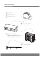
1 Accessories The air conditioning system comes with the following accessories. Use all of the installation parts and accessories to install the air conditioner. Improper installation may result in water leakage, electrical shock and fire, or cause the equipment to fail.
Safety Precautions 2 Read Safety Precautions Before Installation Incorrect installation due to ignoring instructions can cause serious damage or injury. The seriousness of potential damage or injuries is classified as either a WARNING or CAUTION. WARNING Failure to observe a warning may result in death. The appliance must be installed in accordance with national regulations. Failure to observe a caution may result in injury or equipment damage.
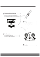
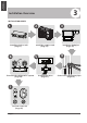
Unit Installation Overview 3 Installation Overview INSTALLATION ORDER 1 3 2 Install the indoor unit (Page 7) 6 Install the outdoor unit (Page 13) 5 MC 4 L N MC Evacuate the refrigeration system (Page 25) 7 Perform a test run (Page 27) Page 6 Install the drainpipe (Page 16) Connect the wires (Page 21) Connect the refrigerant pipes (Page 18)
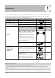
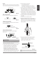
Indoor Unit Parts Air inlet Air outlet Heat exchanger Air filter(inside air-in grill)(optional) Electric control cabinet Drain hose Refrigerant connecting pipe Fig. 4.1 Safety Precautions CAUTION WARNING • Securely install the indoor unit on a structure that can sustain its weight.
Step 2: Hang indoor unit. 1. The size of installation for indoor unit following the Fig.4-3, This unit has installed with air filter. A E N K M H I F B D 3/8” 3/8” L O J 2-Φ 1/8” Φ 3/16” G C 3/8” 3/8” Indoor Unit Installation Please refer to the following diagrams to locate the four positioning screw bolt holes on the ceiling. Be sure to mark the paces where you will drill ceiling hook holes. 2-Φ1/8” Φ 3/16” Table.4-1 MODEL (Btu/h) 24K Fig. 4.
Wood mounting Roof beam Ceiling Hanging screw bolts Fig. 4.4 New concrete bricks Inlay or embed the screw bolts. (See Fig.4.5) (Blade shape insertion) (Slide insertion) Fig. 4.5 Original concrete bricks Use an embedding screw bolt, crock, and stick harness.(See Fig.4.6) 3. Install hanging screw bolts. Cut off the roof beam. Strengthen the point at which the cut was made. Consolidate the roof beam. 4.
Indoor Unit Installation Step 3: Diagrammatic sketch for installing the main body Installing the dust proof net and canvas air passage 1. Install the dust proof net according to the installation manual; 2. Install the canvas air passage underneath the dust proof net. Step 4: Duct and accessories installation 1. The air inlet and air outlet duct should be far enough apart enough to prevent air outlet entering Air Inlet. 2. There is dust filter on the indoor unit. 3.
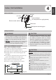
5 Outdoor Unit Installation Outdoor Unit Installation Instructions √ √ √ √ √ The area must be free of combustible gases and chemicals. The pipe length between the outdoor and indoor unit may not exceed the maximum allowable pipe length. If possible, DO NOT install the unit where it is exposed to direct sunlight. If possible, make sure the unit is located far away from your neighbors’ property so that the noise from the unit will not disturb them.
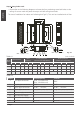
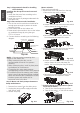
Split Type Outdoor Unit (Refer to Fig 5.4, 5.5, 5.6, 5.10 and Table 5.1) Vertical Discharge Type Outdoor Unit (Refer to Fig 5.7, 5.8, 5.9 and Table 5.2) (Wall or obstacle) Air Outlet H >47”/120cm Fig. 5.4 Outdoor Unit Installation W W Fig. 5.7 H W H Fig. 5.5 D Fig. 5.8 A D (Wall or obstacle) B Fig. 5.6 >11.8” /30cm Air inlet Table 5.1: Length Specifications of Split Type Outdoor Unit (unit: mm/inch) Outdoor Unit Dimensions WxHxD Mounting Dimensions Distance A >11.8” /30cm >11.
11.8” / 30 cm o ck m .8” 11 0 /3 cm fro ba ll wa n lef M t 23.6” / 8” m 0c 20 / 60 P t ron cm o NOTE: Make sure the water drains to a safe location where it will not cause water damage or a slipping hazard. n rig ht nf i Drain Joint Installation Before bolting the outdoor unit in place, you must install the drain joint at the bottom of the unit. (See Fig. 5.12) 1. Fit the rubber seal on the end of the drain joint that will connect to the outdoor unit. 2.
6 Drainpipe Installation The drainpipe is used to drain water away from the unit. Improper installation may cause unit and property damage. NOTE ON DRAINPIPE INSTALLATION • CAUTION Insulate all piping to prevent condensation, which could lead to water damage. • If the drainpipe is bent or installed incorrectly, water may leak and cause a water-level switch malfunction. • In HEAT mode, the outdoor unit will discharge water.
3. Using a 2.5” (65-mm) core drill, drill a hole in the wall. Make sure that the hole is drilled at a slight downward angle, so that the outdoor end of the hole is lower than the indoor end by about 0.5” (12mm). This will ensure proper water drainage (See Fig. 6.5). Place the protective wall cuff in the hole. This protects the edges of the hole and will help seal it when you finish the installation process. The unit with pump. 1. Remove the test cover. Fill the water pan with 2.11 quart of water.
7 Refrigerant Piping Connection Safety Precautions WARNING • Refrigerant Piping Connection All field piping must be completed by a licensed technician and must comply with the local and national regulations. • When the air conditioner is installed in a small room, measures must be taken to prevent the refrigerant concentration in the room from exceeding the safety limit in the event of refrigerant leakage.
Refrigerant Piping Connection Instructions CAUTION The branching pipe must be installed horizontally. An angle of more than 10° may cause malfunction. • DO NOT install the connecting pipe until both indoor and outdoor units have been installed. • Insulate both the gas and liquid piping to prevent water leakage. • Step1: Cut pipes 1. Measure the distance between the indoor and outdoor units. 2. Using a pipe cutter, cut the pipe a little longer than the measured distance.
6. Place flaring tool onto the form. 7. Turn the handle of the flaring tool clockwise until the pipe is fully flared. Flare the pipe in accordance with the dimensions shown in table 7.2. Table 7.2: PIPING EXTENSION BEYOND FLARE FORM Pipe gauge Tightening torque Flare dimension (A) (Unit: in/mm) Min. Max. Ø 1/4” 14.2-17.2 N.m (144-176 kgf.cm) 0.3/8.3 0.3/8.3 Ø 3/8” 32.7-39.9 N.m (333-407 kgf.cm) 0.48/12.4 0.48/12.4 Ø 1/2” 49.5-60.3 N.m (504-616 kgf.cm) 0.6/15.4 15.8/0.62 Ø 5/8” 61.8-75.4 N.
8 Wiring Safety P recautions WARNING DO NOT connect the unit to the power source until all wiring and piping is completed. • Make sure that you do not cross your electrical wiring with your signal wiring. This may cause distortion and interference. • • Connect the out door wires before connecting the indoor wires. • Make sure you ground the unit. The grounding wire should be located away from gas pipes, water pipes, lightning rods, telephone wires or other grounding wires.
Table 8.2: Other World Regions Rated Current of Nominal Cross-Sectional Appliance (A) Area (mm²) ≤ 6 0.75 6 - 10 10 - 16 16 - 25 25- 32 32 - 45 1 1.5 2.5 4 6 b. Using wire strippers, strip the rubber jacket from both ends of the signal cable to reveal approximately 15cm (5.9”) of wire. c. Strip the insulation from the ends. d. Using a wire crimper, crimp u-lugs on the ends. NOTE: When connecting the wires, strictly follow the wiring diagram found inside the electrical box cover. 2.
Using the wire control to set external static pressure (some models) • • You can use the unit’s automatic airflow adjustment function to set external static pressure. CAUTION • After 3 to 6 minutes, the air conditioning unit stops operating once automatic airflow adjustment has finished. Automatic airflow adjustment is the volume of blow-off air that has been automatically adjusted to the quantity rated. 1. Make sure the test run is done with a dry coil.
Power Specifications NOTE: Electric auxiliary heating type circuit breaker/fuse need to add more than 10 A.
MODEL (Btu/h) PHASE FREQUENCY AND VOLT CIRCUIT BREAKER/FUSE(A) PHASE POWER (outdoor) FREQUENCY AND VOLT CIRCUIT BREAKER/FUSE(A) POWER (indoor) ≤36K 37K~60K ≤36K 37K~60K 1 Phase 1 Phase 1 Phase 1 Phase 208-240V 208-240V 208-240V 208-240V 15/10 3 Phase 15/10 3 Phase 15/10 3 Phase 15/10 3 Phase 380-420V 380-420V 208-240V 208-240V 25/20 32/25 32/25 45/35 Inverter Type A/C Power Specifications MODEL (Btu/h) ≤18K 19K~24K PHASE 1 Phase 1 Phase FREQUENCY 220-240V 220-240V AND VOLT CIRCUI
9 Air Evacuation 4. Turn on the vacuum pump to evacuate the system. 5. Run the vacuum for at least 15 minutes, or until the Compound Meter reads -76cmHG CAUTION (-1x10⁵Pa). 6. Close the manifold gauge’s Low Pressure Use a vacuum pump with a gauge reading valve and turn off the vacuum pump. lower than -0.1MPa and an air discharge capacity above 40L/min. 7. Wait for 5 minutes, then check that there has The outdoor unit does not need vacuuming. been no change in system pressure.
Note On Adding Refrigerant CAUTION • Refrigerant charging must be performed after wiring, vacuuming, and the leak testing. • DO NOT exceed the maximum allowable quantity of refrigerant or overcharge the system. Doing so can damage the unit or impact it’s functioning. • Charging with unsuitable substances may cause explosions or accidents. Ensure that the appropriate refrigerant is used. • Refrigerant containers must be opened slowly. Always use protective gear when charging the system.
Test Run 10 Test Run f. Check to see that the drainage system is Befo re Test Run unimpeded and draining smoothly. A test run must be performed after the entire g. Ensure there is no vibration or abnormal system has been completely installed. Confirm noise during operation. the following points before performing the test: 5. For the Outdoor Unit a) Indoor and outdoor units are properly a. Check to see if the refrigeration system is installed. leaking. b) Piping and wiring are properly connected. b.