
Owner and Installation Manual

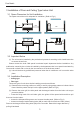
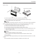
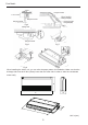
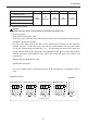
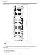
Table Of Contents

Caution:
The power of every indoor unit should be connected in outdoor unit.
①.
Open front panel.
②.
Remove the electrical box cover.
③.
Route the power connection cord from the back of the indoor unit and pull it toward the front
through the wiring hole upward.
④.
Put the 4-core cable through the hole of the chassis and the bottom of the appliance
upward, and then connect the power line and the communication line from the outdoor
unit to the corresponding terminals N(1), 2, 3 , and grounding terminal of the indoor unit.
Wiring shall be done properly as per the wiring diagram. (Note: Be sure the wring terminals
A/B/C/D and piping joints A/B/C/D of the indoor unit match with that of the outdoor unit
respectively).
⑤.
Reassemble the electrical box cover.
⑥.
Reinstall the front panel.
⑦.
Do not use copper tube at interconnection part as the temperature of refrigerant circuit is
high.
Free Match
6
Model A B H C D
CH09UFC230VI
CH12UFC230VI
CH18UFC230VI
CH24UFC230VI
48in
(1220mm)
9in
(225mm)
28in
(700mm)
46in
(1158mm)
11in
(280mm)
3.4 Electrical Wiring
INDOOR UNIT C
INDOOR UNIT B
INDOOR UNIT A
XT XT XT2
OUTDOOR UNIT
N
L
POWER
INDOOR UNIT D
CH36MVCT230VO