
Installation Manual


ALL WIRING MUST BE PERFORMED STRICTLY
IN ACCORDANCE WITH THE WIRING
DIAGRAM LOCATED ON THE INSIDE OF THE
INDOOR UNIT’S WIRE COVER.
Page 17
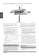
Step 6: Connect signal cable
The signal cable enables communication between
the indoor and outdoor units. You must first
choose the right cable size before preparing it for
connection.
Cable Types
• Indoor Power Cable (if applicable):
H05VV-F or H05V2V2-F
• Outdoor Power Cable: H07RN-F
• Signal Cable: H07RN-F
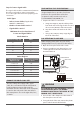
Minimum Cross-Sectional Area of
Power and Signal Cables
Other Regions
Rated Current of
Appliance (A)
Nominal Cross-Sectional
Area (mm²)
> 3 and ≤ 6 0.75
> 6 and ≤ 10 1
> 10 and ≤ 16 1.5
> 16 and ≤ 25 2.5
> 25 and ≤ 32 4
> 32 and ≤ 40 6
CHOOSE THE RIGHT CABLE SIZE
The size of the power supply cable, signal
cable, fuse, and switch needed is determined
by the maximum current of the unit. The
maximum current is indicated on the nameplate
located on the side panel of the unit. Refer to
this nameplate to choose the right cable, fuse,
or switch.
TAKE NOTE OF FUSE SPECIFICATIONS
The air conditioner’s circuit board (PCB) is
designed with a fuse to provide overcurrent
protection. The specifications of the fuse
are printed on the circuit board, such as:
T3.15A/250VAC, T5A/250VAC, etc.
1. Prepare the cable for connection:
a. Using wire strippers, strip the rubber jacket
from both ends of the signal cable to reveal
about 1.57 in (40 mm) of the wires inside.
b. Strip the insulation from the ends of the
wires.
c. Using a wire crimper, crimp u-type lugs on
the ends of the wires.
PAY ATTENTION TO LIVE WIRE
While crimping wires, make sure you clearly
distinguish the Live (“L”) wire from other wires.
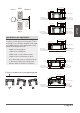
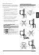
2. Open the front panel of the indoor unit.
3. Using a screwdriver, open the wire box cover
on the right side of the unit. This will reveal
the terminal block.
Terminal block
Wire cover
Screw
Cable clamp
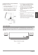
Terminal block
Brown
Black
Gray
Yellow-
green
WARNING
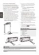
4. Unscrew the cable clamp below the terminal
block and place it to the side.
5. Facing the back of the unit, remove the plastic
panel on the bottom left-hand side.
Fig. 3.9
Indoor Unit
Installation
North America
Appliance Amps (A)
AWG
10 18
13 16
18 14
25 12
30 10
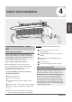
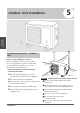
INDOOR UNIT
OUTDOOR UNIT
1 2
3