
Installation Manual


Page 30
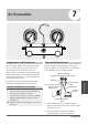
3. Open the low pressure side of the manifold
gauge. Keep the high pressure side closed.
4. Turn on the vacuum pump to evacuate the
system.
5. Run the vacuum for at least 15 minutes, or
until the compound meter reads -76 cm HG
(-10 Pa).
6. Close the low pressure side of the manifold
gauge and turn o the vacuum pump.
7. Wait 5 minutes, then check that there
has been no change in system pressure.
8. If there is a change in system pressure, refer
to Gas Leak Check section for information
on how to check for leaks. If there is no
change in system pressure, unscrew the cap
from the packed valve (high pressure valve).
9. Insert a hexagonal wrench into the packed valve
(high pressure valve) and open the valve by
turning the wrench in a 1/4 counterclockwise
turn. Listen for gas to exit the system, then
close the valve after 5 seconds.
10. Watch the pressure gauge for one minute
to make sure that there is no change in
pressure. The pressure gauge should read
slightly higher than the atmospheric pressure.
Flare nut
Cap
V
alve body
Valve stem
11. Remove the charge hose from the service port.
12. Using hexagonal wrench, fully open both the
high pressure and low pressure valves.
13. Tighten valve caps on all three valves (service
port, high pressure, low pressure) by hand.
You may tighten it further using a torque
wrench if needed.
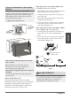
OPEN VALVE STEMS GENTLY
When opening valve stems, turn the hexagonal
wrench until it hits against the stopper. Do not
try to force the valve to open further.
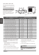
Note on Adding Refrigerant
ADDITIONAL REFRIGERANT PER PIPE LENGTH
Connective Pipe
Length (m)
Air Purging
Method
Additional Refrigerant
< Standard pipe length Vacuum pump N/A
> Standard pipe
length
Vacuum pump
Liquid Side: ø 0.25” (Ø 6.35)
R22:
(Pipe length – standard length) x 30 g/m
(Pipe length – standard length) x 0.32 oZ/ft
Inverter R410A:
Fixed-frequency R410A:
Inverter R410A:
Fixed-frequency R410A:
(Pipe length – standard length) x 15 g/m
(Pipe length – standard length) x 0.16 oZ/ft
(Pipe length – standard length) x 20 g/m
(Pipe length – standard length) x 0.21 oZ/ft
(Pipe length – standard length) x 40 g/m
(Pipe length – standard length) x 0.42 oZ/ft
Liquid Side: ø 0.375” (Ø 9.52)
R22:
(Pipe length – standard length) x 60 g/m
(Pipe length – standard length) x 0.64 oZ/ft
(Pipe length – standard length) x 30 g/m
(Pipe length – standard length) x 0.32 oZ/ft
CAUTION
DO NOT mix refrigerant types.
Fig. 6.2
Air Evacuation
Some systems require additional charging depending on pipe lengths. The standard pipe length varies
according to local regulations. For example, in North America, the standard pipe length is 25 ft (7.5 m).
In other areas, the standard pipe length is 16 ft (5 m). The additional refrigerant to be charged can be
calculated using the following formula:
5