
User's Manual


7
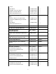
Boom Rotate CW 13 U O2 (S20)
Pole Guide/Platform OPEN 12 V O3 (S20)
Pole Guide/Platform CLOSE 21 W O4 (S20)
Digger Shift HIGH 27 X O5 (S20)
Digger Shift LOW 4 Y O6 (S20)
Auger LATCH 2 Z D4 (R1300)
Auger UNLATCH 20 a D5 (R1300)
Throttle UP 31 b D6 (R1300)
Throttle DOWN 7 c D7 (R1300)
Emergency Power 9 d D3 (R1300)
Electronic Throttle Output (0 to 5V) 1 e O9 (S20) via PWM/V
Converter Board
Hydraulic Tool Valve 43 f D8 (R1300)
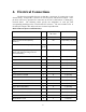
Upper Boom Extended Switch (N.O.
contact)
32 g J2 pin 6 (R1300)
Intermediate Boom Retracted Switch
(N.O. contact)
28 h J2 pin 7 (R1300)
Upper Boom Retracted Switch (N.O.
contact)
8 j J2 pin 8 (R1300)
(not used) — k —
Auger Overstow Switch (N.O. contact)
Input
33 m J2 pin 2 (R1300)
(spare switch input) 15 n J2 pin 3 (R1300)
(spare switch input) 17 p J2 pin 4 (R1300)
Boom Stowed Switch (N.O. Contact)
Input
11 q J2 pin 5 (R1300)
+5V Power for N.O. Switches 42 r J2 pin 1 (R1300)
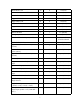
+5V for Proportional Pressure and
Angle Sensors
34 s J3 pin 1 (R1300)
Angle Sensor Input
(-20.00° = 0.2V, +73.12° = 5.0V)
16 t J3 pin 3 (R1300)
Lift Cylinder Piston-Side Pressure
Sensor Input (0 PSI = 0.5V, 3000 PSI =
4.5V)
10 u J3 pin 4 (R1300)