
User Manual
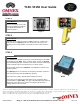


SW 5
SW 1 SW 2 SW 3 SW 4
SW 6
EStop
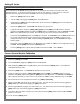
Transmitter / Receiver Replacement and Service
In order to program the
R150
or replace the fuse, you will first need to
remove the circuit board from the housing of the
R150
. This is done by
releasing the two side tabs on the housing, and sliding the connector block
and circuit board out of the housing until the four
STATUS
LED’s are
visible and the
[SETUP]
SW1 button is accessible. See Figure 2.
Also refer to
Setting ID Codes
for a step by step procedure of setting
ID
Codes
to match on both the Transmitter and the Receiver.
Fuse
Status LED’s
[SETUP] SW1
Figure 2
Switch Number Position Output Control Pin Assignment Color Code Function
UP Output 9 B3 Green
DOWN Output 10 B4 Green (Black/White)
UP Output 7 B1 White (Red/Black)
DOWN Output 8 B2 Red (Black/White)
UP Output 5 A10 Orange (Black)
DOWN Output 6 A12 Orange (Red)
UP Output 3 A9 White (Red)
DOWN Output 4 A11 Blue (Red)
UP Output 11 B5 White
DOWN Output 12 B6 Orange
UP Output 1 A7 Orange (Green)
DOWN Output 2 A8 Red (Green)
Released
Engaged
EStop
EStop Output A5
Driver Power
Driver Power Input A2
]--
Jumpered Externally
Proportional Control
9 to 30VDC
Ground
A6
A3
Red
Black
T150 / R150 Switch Function Table
A4 Green (Black)Output 13
SW5
SW6
Trigger
SW1
SW2
SW3
SW4
Power
Ground