
User Manual


R150 Relay Outputs
A4
B1
A7
A8
A9
A11
A10
A12
B2
B3
B4
B5
B6
Power
EStop
R150 Internal
Ground
A3
Internal Power
A6
A5
A2
Internally Fused
1
13
EStop Out
Driver Power Input
Jumpered on wiring harness
Troubleshooting
Inputs and Outputs
Replaceable Parts
Inputs
4 x 0-5VDC analog inputs (factory
configurable only)
Outputs
Option 1
13 x Form
A
relay, monitored, 3A max.
each, total combined current 10A
Option 2
12 x Form
A
relay, monitored, 3A max.
each, total combined current 10A max.
1 x
Proportional Control
Fuse
MINI® Fuse Type,10A LittelFuse
OMNEX (p/n F0047) or equiv.
Mating Plugs
OMNEX (p/n’s J0418 / J0419)
Pins
OMNEX (p/n J0417)
Sealing Plug
OMNEX (p/n J0421)
Wedge
OMNEX (p/n J0420)
Switches
OMNEX (p/n S0042)
EStop Switch
OMNEX (p/n S0072)
EStop Contact Block
OMNEX (p/n S0071)
Batteries
OMNEX (p/n B0010) 4 x AA
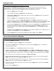
I/O Diagram Deutsch Connector Pin Assignments
Bldg. 74 – 1833 Coast Meridian Road, Port Coquitlam, BC, Canada V3C 6G5
5.13”
4.00”
AB
4.92”
7.87”
4.13”
Dimensions
WARRANTY
OMNEX Control Systems Inc. Warrants to the original purchaser that the OMNEX
products are free from defects in materials and workmanship under normal use and
service for a period of ONE YEAR, parts (EXCLUDING: SWITCHES, CRYSTALS, OR
PARTS SUBJECT TO UNAUTHORIZED REPAIR OR MODIFICATION) and labor
from the date of delivery as evidenced by a copy of the receipt. OMNEX’s entire
liability and your exclusive remedy shall be, at OMNEX’s option, either the (a) repair
or (b) replacement of the OMNEX product which is returned within the warranty period
to OMNEX freight
collect
by the OMNEX APPROVED carrier with a copy of the
purchase receipt and with the return authorization of OMNEX. If failure has resulted
from accident, abuse or misapplication, OMNEX shall have no responsibility to repair
or replace the product under warranty. In no event shall OMNEX be responsible for
incidental or consequential damage caused by defects in its products, whether such
damage occurs or is discovered before or after replacement or repair and whether or
not such damage is caused by the negligence of OMNEX Control Systems Inc.
Neither OMNEX nor its Distributors shall be liable for any delay or failure of the
performance of any of its obligations under this agreement caused by acts of God,
labor disputes, embargoes, boycotts, shortage of parts or any cause beyond its
reasonable control.
Neither OMNEX nor its Distributors shall be responsible for incurred costs associated
with border clearance or with the
delay of the OMNEX products in transit to OMNEX.
Any charges associated with the return of the OMNEX products may be subject
to billing to the original purchaser in the event that the OMNEX products are
NOT covered by the warranty as noted above.
Output 6
Output 4
Output 5
Output 3
Output 2
Output 1
Input 1
Driver Power
GND
Output 13
EStop Output
Power
2
3
4
5
6
1
12
11
10
9
8
7
6
5
4
3
2
1Output 7
Output 8
Output 9
8
9
10
11
12
7
Output 10
Output 11
Output 12
Connector A (Grey)
Connector B (Black)
Factory Configurable Only
RS485 EN
RS485 A
RS485 B
Input 3
Input 4
Input 2
The
R150
has 4 LED’s that are used to indicate device status:
ESTOP LED
!
!!
!!!!
GREEN – indicates RUN
RED – indicates ESTOP
Flashing RED – indicates fuse blown or relay fault
FUNCTION/FAULT LED
!!
!!
!!!
GREEN – indicates function ON, no fault
RED – indicates no voltage to relay, short to ground or blown
fuse
Flashing RED – indicates short to supply or shorted output relay
Not lit – indicates no function
LINK LED
!!!
!!
!!
GREEN – indicates Link
RED – indicates No Link
STATUS LED
!!!!
!!
!
GREEN – indicates STATUS OK
RED – indicates unrecoverable fault; requires factory authorized
service
Flashing RED – indicates low battery
The
T150
has 2 LED’s that display the mode and status of the device
ACTIVE LED
!
!!
!
"
""
"
!
!!
!
Momentarily ON or Flashing indicates Power Up procedure or
Programming status. LED will flash with each function during
normal operation indicating Transmit Status to the R150 is good
LOW BATT. LED
!
!!
!
"
""
"
!
!!
!
Momentarily ON or Flashing indicates Power Up procedure or
Programming status
During normal operation, this LED will only flash to indicate
battery low
ACTIVE and LOW BATT. LED’s
!
!!
!
"
""
"
!
!!
!
Both LED’s flashing in sync indicates one of the switches is stuck
NOTE:
The Current Control Module may be
installed as an option giving the user Proportional
Control on output 13 of the
R150
- refer to
Current
Control Module Calibration
for Proportional
Calibration procedures.
The Proportional Control option is available from
the factory in either Voltage Control, PWM or
Current Control.
R150
The
R150
is internally fused as
shown using a 10A MINI® fuse.
Follow the steps in Transmitter /
Receiver replacement to open
the
R150
for fuse replacement.