
User's Manual


XPD900 User Manual Revision 1.2
Company Confidential Information Page 7 of 10
7.2 ISED Statement
In accordance with the requirement of RSS-GEN 8.4, the following statement shall be included in the
user manual.
This device contains licence-exempt transmitter(s)/receiver(s) that comply with Innovation, Science
and Economic Development Canada’s licence-exempt RSS(s). Operation is subject to the following two
conditions:
1. This device may not cause interference.
2. This device must accept any interference, including interference that may cause undesired
operation of the device.
Le présent appareil est conforme aux CNR d'Industrie Canada applicables aux appareils radio exempts
de licence. L'exploitation est autorisée aux deux conditions suivantes :
(1) l'appareil ne doit pas produire de brouillage, et
(2) l'utilisateur de l'appareil doit accepter tout brouillage radioélectrique subi, même si le brouillage
est susceptible d'en compromettre le fonctionnement.
8 Antennas
The radio module is only certified for certain antenna. To avoid triggering additional certification work,
the following certified antenna and trace designs must be used with host devices that integrate the
XPD900 radio module.
Trace design is the connection from the module to an antenna via the host’s PCB microstrip trace to an
external connector, trace antenna, or component (chip) antenna on a PCB. This includes the passive
matching components on the host PCB, (KDB 996369 D02 Q11). Note the RF traces, dimensions, thickness,
passive components, layout, dielectric constant, impedance, and PCB stack up on new host product PCB
must not change from the approved designs.
There is a total of 8 antenna that were approved for use with the radio module. There are four physical
antennas radiating elements, and the remainder are antenna trace designs. The module test report, “The
Module Test Report, “E10788-2103_Cooper Electrical_XPD900_FCC-ISED_Rev-1.0.pdf” includes antenna
information certified with the module.
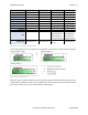
The following antennas are approved for use with the module. For antenna 3 and 4 the trace design
must be duplicated as explained above.
When using the internal antennas, antenna 3 and 4, ensure that the PCB trace design and cable of the
new host product matches one of the host trace designs listed in Table 3.