DCM 437 CURRENT BRIDGE AMPLIFIER USER’S GUIDE www.cooperinstruments.
Features • Complete Strain Gage Bridge Signal Conditioner • 4-20 mA or 0-20 mA Output • Output Capable of Driving 1000 ohm Loop • Bridge Balance with 68% Tare Offset Capability • High Gain Amplifier; Can Accept Live Load Signals as Low as 3 mV and Provide 16 mA Output Span • Sufficient Excitation Current for Five Load Cells • Powered by 10 to 36 VDC Unregulated • Rugged Epoxy Encapsulated Design Applications • Weighing with Load Cells • Process Control Add-on Loops Description The Model DCM 437 is a self-co
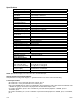
Specifications 4 to 20 mA; 0 to 20 mA Output Current Span 3 mV to 62 mV Input for 16 mA Span 12 mA Zero Adjust 1 microamp/°C typical Temperature Coefficient 0° to 55°C 4 microamp/°C maximum Hysteresis 50 microamp maximum Amplifier Cell Sensitivity 0.3 mV/V to 6.2 mV/V (10 Volts Excitation) Linearity 0.005% typical Temperature Stability 50 ppm/°C Hysteresis 0.1% of span maximum Input Bias Current 150 pA maximum Input Noise: DC to 10 Hz 4 microvolts P-P maximum Common Mode Input 0 to +7.
E. Determine the voltage of the power supply to be used and adjust within the 10 to 36 volt range if necessary before connecting to the power pins, 1 and 2. F. Verify that the hook up procedure is complete. G. Turn on the power supply and check the bridge excitation supply. II. Calibration Procedure A. Set the GAIN SWITCH position 1 ON and all others OFF. B. Short the signal input pins 9 and 10 together with a clip lead. Adjust the COARSE and FINE OFFSET pots, C and B, for zero or 4 mA output current.
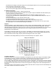
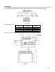
Bridge Balance The Bridge Balance pot provides up to 68% of full-scale tare weight adjustment when using a 350-ohm, 3mV/V load cell. The DCM 437 can then be adjusted to provide full span output with only about 10% of the cell’s range. DCM 437 Gain Switch Bridge Output Signal for: Gain Switch Position “ON”: 1 2 3 4 5 0 to 20 mA 50mV to 62.5mV 25mV to 50 mV 12.5mV to 25mV 6.25mV to 12.5mV 3.125mV to 6.25mV 4 to 20 mA 40mV to 50mV 20mV to 40mV 10mV to 20mV 5mV to 10mV 2.
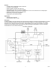
Screw Terminal 1 2 3 4 5 Terminal Strip Assignments Screw Function Function Terminal +DC POWER +EXCITION 6 - DC POWER CURRENT OUTPUT 7 -SENSE AMPLIFIER CMN 8 -EXCITATION -INPUT 9 +SENSE +INPUT 10 WARRANTY REPAIR POLICY Limited Warranty on Products Any Cooper Instruments product which, under normal operating conditions, proves defective in material or in workmanship within one year of the date of shipment by Cooper will be repaired or replaced free of charge provided that a return material authorization is