User Guide DCM 470 Cooper Instruments & Systems PO Box 3048 Warrenton, VA 20188 800-344-3921 www.cooperinstruments.com PH: 540-349-4746 FAX: 540-347-4755 CF 138 DCM 470 Rev.
Table of Contents Default Settings ......................................................................................................................................... iv Connections ............................................................................................................................................... iv Standard Span & Zero Adjustment .......................................................................................................... v Shunt Readings ....................
Default Settings • • • Input Range: 0 to +/-2 mV/V Excitation Voltage: 10 VDC Output Range: +/-10 VDC, 4-20 mA Connections Note: Do not connect the device to the power supply when the power supply is already on! (1) For 6 wire sensors connect +Sense to +Excitation and –Sense to –Excitation or EM1000-C Ground (2) Only available with current output option CF 138 DCM 470 Rev.
Standard Span & Zero Adjustment Once all of the connections are complete, you can begin to set up the sensor/amplifier system. You will need to have the output from the DCM 470 connected to a device so you can read the voltage or current. To set up the system, follow the steps below: 1. Apply a known load to the sensor. 2. Allow the sensor to settle. 3. Use a screwdriver to adjust the span that correlates with that load. 4. Remove the load. 5. Allow the sensor to settle. 6. Adjust the zero. Ex.
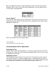
1. Determine the value of the shunt resistor needed 2. Connect the shunt resistor in the spot labeled ‘RSH’. 3. Press the pushbutton that corresponds to the shunt. 4. While the shunt is enabled and the DCM 470 is reading the simulated load, adjust the span (described above) to the correct output. Ex. If you are using a 2 mV/V sensor with a 350 Ohm bridge and the default 60.4 k Ohm resistor on the DCM 470, then the simulated load would be approximately 72% of R.O. You can then adjust the span to 7.
Ex. If your application requires a lower output voltage than 10 VDC, then the 5 VDC option is available to use. All you have to do is flip the DIP switch from the down position to the up position. Polarity There are two polarities available on the DCM 470: reverse, and straight (default). To select the polarity, simply flip the DIP switch to the appropriate configuration. Ex.
Ex. If your application requires a higher bandwidth in order to account for the higher frequency signals, such as those from dynamic applications, then you would want to use the higher setting bandwidth. Current Setting (4) There are four current output settings available on the DCM 470: 0-16 mA, 0-20 mA, 420mA (default), and 5-25 mA. To select the current, simply flip the DIP switches to the appropriate configuration. Note: Only available with current output option.
Warranty Limited Warranty on Products Any Cooper Instruments product which, under normal operating conditions, proves defective in material or in workmanship within one year of the date of shipment by Cooper will be repaired or replaced free of charge provided that a return material authorization is obtained from Cooper and the defective product is sent, transportation charges prepaid, with notice of the defect, and it is established that the product has been properly installed, maintained, and operated wit