
Manual

CF 66 28 Rev. C 2/05
• “00010”
• “00020”
• “00050”
• “00100”
• “00200”
This menu item may be automatically updated by a transducer’s Signature Module.
DISPLAY.UNITS Menu Item
Specifies the four-character label that is displayed to the right of the channel’s values.
This menu item doesn’t change the mathematical scaling of the channel’s values; that can be changed by altering
the “CALIBRATION DATA->FULL SCALE VALUE” menu item and then performing a re-calibration.
When a character position is flashing press the [UP] or [DOWN] button to change the character. Press [ENTER] to
advance to the next character.
This menu item may be automatically updated by a transducer’s Signature Module.
DISPLAY.AVERAGE Menu Item
Controls the speed with which the channel’s display values will update. Display averaging does not affect the
channel’s analog output or its peak/valley detection, which will proceed at the speed selected by the “OPERATION-
>FREQ.RESPONSE” menu item. The choices are:
• “ON” means that the display will update four times each second. The channel’s values will be averaged for ¼
second, then displayed.
• “OFF” means that the channel’s display will update as quickly as possible.
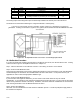
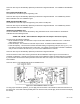
10.5.3 AUXn FUNCTION Menu Items
The AUX1 FUNCTION and AUX2 FUNCTION menu items determine what happens when the Auxiliary Function
pins (labeled as “AUX1” and “AUX2”) on the channel’s connector are activated. These pins are “activated” when
they are connected to the (-) Signature (labeled as “-MEM”) pin. The choices are:
• “DISABLED” means that activating the pin does nothing.
• “TRACK HOLD” means that the tracking, peak and valley values will not be updated.
• “HIGH/LOW HOLD” means that the peak and valley values will not be updated.
• “HIGH/LOW CLEAR” means that the peak and valley values are reset.
• “TARE ON” activates the channel’s Tare function (resets it to zero).
• “TARE OFF” deactivates the channel’s Tare function.
As the Auxiliary Function pins are not isolated, it is recommended that a push-button switch or relay is used to
connect these pins to the (-) Signature pin.
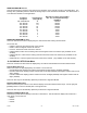
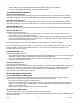
10.5.4 CALIBRATION TYPE Menu Item
This chooses the type of calibration technique to be used. There are three methods that can be used to calibrate
the transducer to the Input Channel. Each has advantages and disadvantages as described in the table below.
Table 10-1: Comparison of Calibration Types
Shunt Calibration mV/V Calibration 2-, 3-, or 5-point Known
Load Calibration
RECOMMENDED
…for most applications No Yes No
…when frequently swapping transducers Yes Yes No
…when best possible accuracy required No No Yes
PROS and CONS
Relative accuracy Good Better Best
Requires actual, calibrated loads to be
applies
No No Yes
Automatically calibrates with Signature Yes Yes No