
Manual
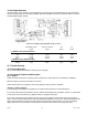

CF 66 35 Rev. C 2/05
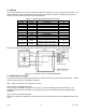
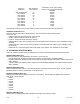
10.6.3 Output Selection
Jumpers located on the channel’s circuit board determine what outputs are generated when the value selected to
drive the Analog Output (from the DAC.CHANNEL and DAC.SOURCE menu items) equals the DAC.FULL SCALE
and DAC.ZERO SCALE settings.
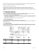
Figure 10-3: Digital-to-Analog Output Jumper Locations
DAC.ZERO SCALE DAC.FULL SCALE J30 J31
Output Output jumper jumper
CHANNELS WITH VOLTAGE OUTPUT
0-5V 2.5 Volts 5 Volts open closed
±5V 0 Volts 5 Volts open open
0-10V 5 Volts 10 Volts closed closed
±10V 0 Volts 10 Volts closed open
CHANNELS WITH CURRENT OUTPUT
4-20mA 4mA 20mA open open
4-20mA 12mA 20mA open closed
10.7 Troubleshooting
10.7.1 Error Messages
See “Error Messages” for information relating to error messages.
10.7.2 Common Problems and Solutions
Erratic Display
Check electrical connections for continuity and the transducer’s wiring code from its Certificate of Calibration.
Make sure that the load on the transducer is constant.
Check millivolt input to the (+)Signal (“+SIG”) and (-)Signal (“-SIG”) pins with a voltmeter.
+OVLD or –OVLD on Display
is overranging or underranging the amplifier circuit. Make certain all wires are connected properly.
If you remove all load from the transducer and you still see this message, the (+)Excitation (“+EXC”) or (-)Excitation
(“-EXC”) pins may be shorted to the (+)Signal (“+SIG”) or (-)Signal (“-SIG”) pins.
If you remove all load from the transducer and you get a numeric reading, the transducer may have a high zero
offset. Use the channel’s SETUP menu and set DIAGNOSTICS-DISPLAY ADC to “ON”; in the RUN mode this will
allow the [VALUE] button to display raw A/D readings as a percentage of its full-scale. If the raw A/D readings
display more than ±10% when there is no load on the transducer, the transducer has a high zero offset.