
Manual
CF 66 43 Rev. C 2/05
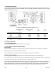
11.5.8 DIAGNOSTICS Sub-Menu
DAC FULL SCALE Menu Item
When this menu item is selected, the Analog Output of the channel is forced to its full-scale output, then DAC
UPDATED is displayed. This is useful when calibrating or trimming the readout connected to the Analog Output.
DAC ZERO SCALE Menu Item
When this menu item is selected, the Analog Output of the channel is forced to its zero-scale output, then DAC
UPDATED is displayed. This is useful when calibrating or trimming the readout connected to the Analog Output.
VERSION INFO Menu Item
This menu item displays the part number and revision level of the firmware used by this channels microprocessor.
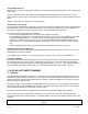
DISPLAY ADC Menu Item
The options for this menu item are:
• “OFF” will allow the [VALUE] button to cycle through “TK” (tracking value) “HI” (peak value) and “LO” (valley
value). This is the recommended option.
• “ON” will allow the “AD” (percentage of the Analog-to-Digital converter’s full-scale digitizing capability) display
source to be available along with the “TK” (tracking value), “HI” (peak value) and “LO” (valley value) when the
[VALUE] button is pressed on the front panel.
The Analog-to-Digital converter counts are displayed as a percentage from –100.00% to 100.00%.
This can be used to establish the transducer’s electrical null prior to mounting. See “Electrical Null and Transducer
Mounting” in Section 11.6 for this procedure.
LINEARIZATION Menu Item
The options for this menu item are:
• “ON” will allow linearization data obtained from a 3-Point or 5-Point Known Displacement Calibration to
affect a channel’s scaled values. This is the recommended option.
• “OFF” will not allow linearization data to affect the channel’s scaled values.
DISABLE CHANNEL Menu Item
The options for this menu item are:
• “ON” will bypass the INITIALIZE and RUN modes of the channel. The track, peak and valley values of the
channel are forced to 0.
• “OFF” will allow normal operation of the channel.
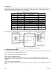
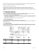
11.6 Electrical Null and Transducer Mounting
11.6.1 Overview
The mechanical travel of an LVDT transducer is not the same as its usable measuring range. All LVDTs exhibit
some non-linearity near the ends of its armature’s mechanical travel. To insure that the LVDT will be used in its
linear measuring range, its electrical null point must be determined. This electrical null point is the armature
position, which produces the minimal electrical signal output. After electrical null has been established, the LVDT is
clamped down into final position in its mounting fixture.
As long as the LVDT remains clamped in this position, you do not need to reestablish the electrical null prior to
every calibration.
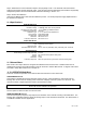
11.6.2 Procedure
Step 1: Use the channel’s SETUP menu and set DIAGNOSTICS-DISPLAY ADC to “ON”. Exit the SETUP menu
and re-start the instrument.
Step 2: Display the channel to which the LVDT is connected. Press and release the [VALUE] button until the “AD”
display source is shown. This is the raw analog-to-digital converter readings displayed as a percentage of its full-
scale (-100% to +100%).