
Manual


CF 66 51 Rev. C 2/05
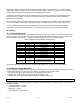
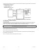
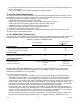
Figure 12-7: Excitation and Signal Jumper Locations on the High-Level Input Channel
12.4 Calibration Procedure
If you are not familiar with operating the instrument in the SETUP menu mode, see “SETUP Menu mode”. A listing
of all menu items is given in “Setup Menu Reference”.
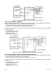
Step 1: Wire the transducer to the channel’s connector.
Step 2: Set the Excitation and Signal jumpers appropriate for the transducer, amplifier or DC-DC LVDT.
Step 3: Enter the CALIBRATION TYPE.
There are two methods that can be used to calibrate the transducer to the Input Channel. Each has advantages
and disadvantages as described in the CALIBRATION TYPE menu item section. It is important to know your
application in order to select the appropriate calibration type.
Step 4: Enter the CALIBRATION DATA
Otherwise, consult the Certificate of Calibration for the transducer when entering information in the CALIBRATION
DATA sub-menu.
Step 5: Perform the calibration.
Using the CALIBRATE menu item starts the calibration process. You will be prompted to apply loads to the
transducer as required.
12.5 Specifications
TRANSDUCER INPUT
Transducer types Amplified with voltage or current output, (field selectable)
Excitation voltage
(1)
±15 VDC @ 40 mA max.
+28 VDC @ 75 mA max.
+12 VDC @ 40 mA max.
(field selectable)
Transducer full-scale output
±1, ±5, ±10 VDC
4-20 mA (field selectable)
Calibration Type Shunt, or 2-, 3- or 5-point known load
A/D Converter 24-bit Sigma-Delta
Low-pass filter Digital, 24-tap FIR
Resolution & Frequency Response
See “FREQ. RESPONSE” Menu Item, Section 12.6.1
INSTRUMENT-ONLY ACCURACY
(Sense wires used; Frequency Response setting <=16Hz; Linearity,
repeatability & hysteresis)